📐 "First 50 Enterprise Queries Get Custom 3D Warehouse Design" Plan
For engineering managers, system integrators, and warehouse operations leaders, the blueprint phase of an automation project is where success is first forged—or where costly failures silently take root. The challenge is universal: transforming a conceptual layout into a build-ready, technically sound plan without getting bogged down in the painstaking creation of foundational component models. The search for reliable, dimensionally accurate modular platform CAD drawings often becomes a critical path obstacle.
This is precisely why a leading provider of integrated warehouse automation solutions has dismantled this barrier. They offer an extensive, proprietary library of free modular platform CAD drawings, providing engineers with immediate access to manufacturer-verified digital models. These are not simplistic symbolic blocks; they are intelligent, data-rich modular platform CAD drawings that serve as the digital twin of physical components, enabling flawless integration of AGV pathways, ASRS foundations, and automated mezzanines. This initiative moves beyond mere lead generation; it represents a fundamental shift towards a collaborative, efficient, and de-risked design process for the entire industry.
The Indispensable Role of Precision CAD Data in Modern Warehouse Systems
In the realm of high-throughput distribution centers and fully automated factories, approximation is the enemy of efficiency. A discrepancy of a few millimeters in a digital model can manifest as a catastrophic misalignment on the production floor, leading to system downtime, safety incidents, and six-figure cost overruns. The integrity of the entire automated ecosystem—from the silent dance of Automated Guided Vehicles (AGVs) to the soaring vertical efficiency of Automated Storage and Retrieval Systems (ASRS)—rests upon the absolute precision of its underlying structures.
The modular platform CAD drawings used in the planning phase are the DNA of this ecosystem. They are the first and most critical checkpoint for ensuring that every component, from a simple bolted connection to a complex multi-level platform, fits perfectly within the grand design.
These foundational modular platform CAD drawings do more than just outline shapes; they communicate intent, specification, and compatibility. When a systems engineer imports a manufacturer’s modular platform CAD drawings into a master layout, they are not just placing geometry; they are integrating certified load capacities, material specifications, and connection protocols.
This level of detail is non-negotiable for performing accurate Finite Element Analysis (FEA), conducting virtual clash detection, and ensuring compliance with international standards like ISO 14122 or OSHA. The availability of high-fidelity modular platform CAD drawings directly correlates with project velocity, cost certainty, and long-term operational reliability. Firms that leverage these specialized modular platform CAD drawings position their projects for success from the very first line drawn in the digital space.
Deconstructing the Anatomy of a High-Value Modular Platform CAD Drawing
What separates a generic, potentially risky CAD file from a high-value, engineering-grade modular platform CAD drawing? The distinction lies in the embedded data and adherence to real-world manufacturing tolerances. A superior modular platform CAD drawing is a comprehensive information package.
Parametric Intelligence: The best modular platform CAD drawings are often parametrically modeled, allowing engineers to adjust key dimensions within a validated range. This flexibility means a single, master modular platform CAD drawing can generate multiple valid configurations for review.
Metadata-Rich Environment: Beyond the lines and arcs, these drawings contain metadata such as part numbers, material grades (e.g., S355JR steel), surface treatment specifications (e.g., powder-coating RAL 9005), and weight. This turns the modular platform CAD drawing into a bill-of-materials precursor.
Layer Standardization: Professional-grade modular platform CAD drawings utilize a logical layer structure, separating structural elements, weld symbols, dimensions, and annotations. This allows for easy manipulation within the client’s master drawing, improving clarity and workflow efficiency.
Detailed Connection Geometry: Every bolt hole, shear tab, and splice connection is modeled to scale. This allows for precise coordination with concrete embeds and other structural elements, preventing the all-too-common issue of misaligned anchor bolts during installation.
A Strategic Resource: The Business Case for Free Manufacturer CAD Drawings
The decision to provide a comprehensive library of free modular platform CAD drawings is a strategic one, rooted in a deep understanding of the client’s design process. This approach signals a shift from a transactional supplier relationship to a collaborative partnership.
For the engineering firm, the benefits are immediate and substantial. It compresses the project timeline by eliminating days or even weeks of modeling time. It mitigates risk by ensuring that the design is based on a manufacturer’s actual product data, not a best-guess approximation. It elevates the role of the engineer, allowing them to focus on system-level optimization and value engineering rather than on the tedious recreation of standard components.
For the provider, this library of free modular platform CAD drawings serves as a powerful qualifier. It attracts a specific, highly valuable audience: professionals who are actively engaged in the technical design of a live project. An individual searching for a generic 3D model of a pallet rack might be a student, but a professional searching for specific modular platform CAD drawings for an AGV integration platform is undoubtedly a serious decision-maker. By providing immediate value, the provider embeds its standards and components into the project’s DNA at the earliest possible stage.
When the design is finalized, the path to a formal quote is not a cold call; it is a continuation of a dialogue that began with the download of a trusted modular platform CAD drawing. This process naturally filters out casual inquiries and ensures that incoming requests for quotation are backed by a mature, well-defined design.
DXF vs. DWG: Selecting the Right Format for Your Workflow
The provider’s library typically offers these essential modular platform CAD drawings in both DXF and DWG formats, a critical consideration for professional usability. The DXF (Drawing Exchange Format) file is the universal translator of the CAD world. As an open standard, it guarantees that the geometric and layering information from the modular platform CAD drawings can be imported into virtually any CAD, CAM, or CNC software platform without corruption. This is indispensable for collaborating with external stakeholders or for preparing files for plasma cutting or other fabrication processes.
The DWG (DraWinG) format, while native to Autodesk’s AutoCAD, is so pervasive in the AEC (Architecture, Engineering, and Construction) industry that it functions as a secondary standard. A DWG file from the library of modular platform CAD drawings often preserves more intelligent object data, dynamic blocks, and xref capabilities, which can be crucial for complex, multi-disciplinary drawings. The availability of both formats ensures that the engineer can work within their established ecosystem without being forced into time-consuming and error-prone file conversions. This thoughtful provision underscores the practical, user-centric design of the entire modular platform CAD drawings library initiative.
Engineering for Dynamic Loads: CAD Drawings for AGV and Robotic Systems
The structural demands placed on a platform supporting mobile robots are fundamentally different from those for static storage. An Automated Guided Vehicle (AGV) or Autonomous Mobile Robot (AMR) does not apply a simple, constant load. It introduces dynamic forces: impact loads from starting and stopping, vibrational forces from uneven flooring or joint transitions, and torsional stresses from turning maneuvers. Standard modular platform CAD drawings for standard applications are insufficient here. The modular platform CAD drawings required for AGV applications must be engineered with these dynamic factors hard-coded into their very design philosophy.
When an engineer downloads specialized modular platform CAD drawings for an AGV pathway, they are accessing models that have been validated for these unique conditions. The drawings include specific callouts for dynamic load capacity ratings, which are often significantly different from static load ratings. Furthermore, these specialized modular platform CAD drawings will detail critical attributes like maximum allowable deflection over a given span. Excessive deflection can disrupt the navigation systems of laser-guided AGVs, leading to operational failures.
The models may also include predefined mounting points or raceways for the integration of guidance system infrastructure, such as magnetic tape, optical sensors, or LiDAR units. By utilizing these purpose-built modular platform CAD drawings, the design team can simulate the real-world operating environment digitally, identifying and mitigating potential issues long before the first panel is fabricated.
The Critical Interface: Modeling the AGV-to-Platform Transition
One of the most nuanced aspects detailed in high-quality modular platform CAD drawings is the transition zone—where the AGV moves from the concrete floor onto the modular platform. A poorly designed transition can cause vehicle stalling, load shifting, or accelerated wear on tires and drivetrains. Expertly crafted modular platform CAD drawings will provide detailed ramp profiles, specifying the exact angle of incline and the required radius for a smooth approach and departure.
The texture of the platform surface, often achieved with a serrated or grip-strut decking, is also a consideration that can be specified within the metadata of the modular platform CAD drawings, ensuring adequate traction for the AGV’s wheels in all conditions.
The Foundation of Precision: CAD Drawings for Automated Storage and Retrieval Systems (ASRS)
If AGV systems demand dynamic resilience, then Automated Storage and Retrieval Systems (ASRS) demand absolute, unwavering stability. An ASRS is a ballet of high-speed, high-precision machinery operating within tolerances often measured in single-digit millimeters. The supporting platform is not merely a floor; it is the foundational datum for the entire storage matrix. Any deflection, settlement, or misalignment in this foundation will be amplified vertically, potentially leading to misaligned crane rails, dropped loads, and catastrophic system failure.
The modular platform CAD drawings created for ASRS integration are therefore among the most rigorous produced. They function as the critical liaison between the structural civil foundation and the high-precision storage hardware. These modular platform CAD drawings provide exhaustive detail on several fronts. First, they specify the exact locations, sizes, and embedment depths of anchor bolts with surgical precision.
The tolerance for these anchor points, often as tight as +/- 2mm, is clearly annotated within the modular platform CAD drawings. Second, the drawings include precise leveling and shimming details, providing a method to achieve the perfect plumbness required for the ASRS upright frames.
Furthermore, the modular platform CAD drawings will illustrate the interface between the platform’s primary steel and the ASRS uprights, often showing custom-fabricated base plates or welded connections that create a monolithic, unified structure. The load tables referenced by these modular platform CAD drawings account not only for the static weight of the stored inventory but also for the dynamic forces imparted by the accelerating and decelerating cranes.
Using these comprehensive modular platform CAD drawings, a civil engineer can design the concrete pad with exact loading information, and the ASRS installer receives a certified foundation upon which to build. This level of integration, facilitated by trusted modular platform CAD drawings, is what separates a smoothly commissioning system from a problematic, delay-ridden installation.
From Digital Model to Certified Calculation: The Engineering Package
It is vital to understand that while the downloaded modular platform CAD drawings provide the geometric and specification foundation, they are the starting point for a formal engineering review. When a client submits their completed layout—which incorporates these modular platform CAD drawings—for a official quote, the provider’s engineering team initiates a comprehensive validation process. This process uses the data from the modular platform CAD drawings as input for sophisticated structural analysis software. The outcome is a stamped engineering drawing package, which includes:
Certified Load Calculations: Site-specific verification of the structure’s capacity under the proposed loading conditions.
Foundation Load Recommendations: Detailed point loads and reactions for the civil engineer.
Assembly Sequence Diagrams: Step-by-step guides for efficient and safe installation.
This seamless transition from accessible modular platform CAD drawings to a certified engineering package is the core of the value proposition, ensuring regulatory compliance and structural safety.
Beyond the Platform: A Holistic Library of Integrated Components
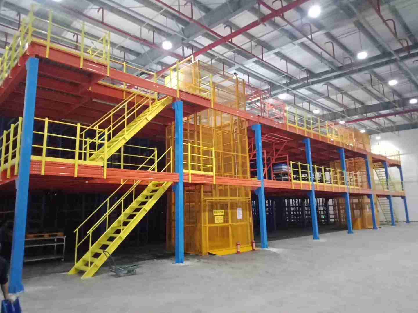
The value of a centralized resource for modular platform CAD drawings multiplies when it encompasses the entire subsystem ecosystem. A platform is ineffective without safe access, perimeter protection, and integrated material handling equipment. A world-class library of modular platform CAD drawings will therefore include a wide array of complementary components, all modeled to the same exacting standards.
Staircases and Ladders: These are not off-the-shelf models but are designed to integrate perfectly with the platform system’s grid and height. The modular platform CAD drawings for staircases will include details for handrails, mid-rails, and kick plates compliant with OSHA 1910.25 or similar standards.
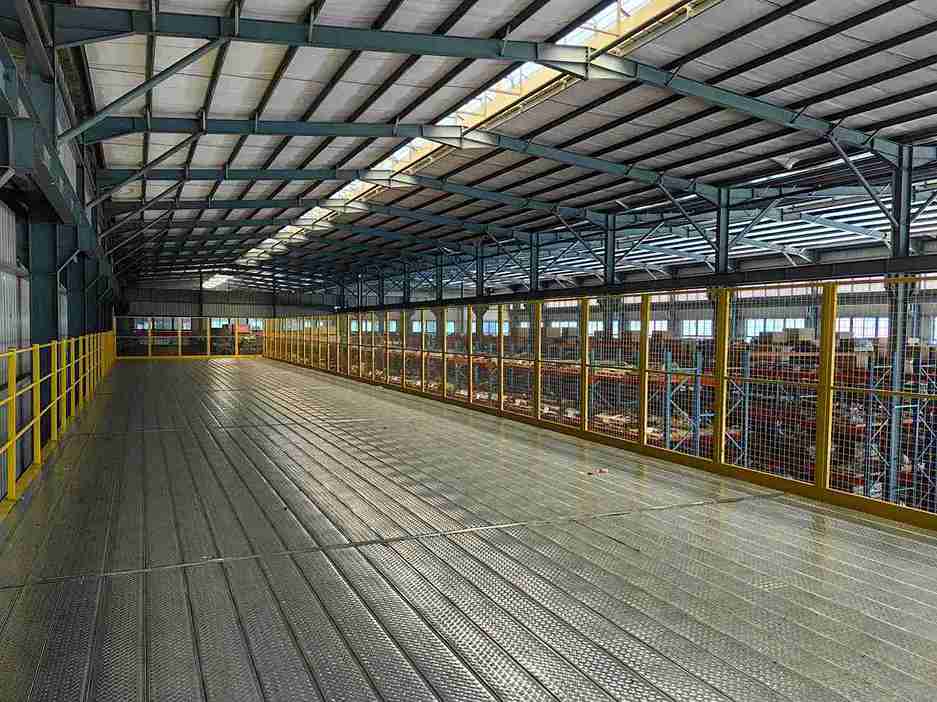
Guardrail Systems: Complete modular platform CAD drawings for guardrails, including posts, top rails, and toe boards, are essential for designing a safe working environment. These drawings will specify heights, mesh infill options, and gate locations.
Conveyor Support Structures: Rather than designing custom steel for every conveyor run, engineers can utilize pre-engineered modular platform CAD drawings for conveyor bridges, support legs, and transition structures. This ensures that the conveyor is supported at the correct height and alignment, maintaining the integrity of the material flow path.
Column Protectors and Bollards: Proactive safety and asset protection can be designed directly into the layout using modular platform CAD drawings for these common accessories.
This holistic approach allows a project team to design an entire mezzanine level or automated work cell using a unified, compatible family of components, all sourced from the same comprehensive library of modular platform CAD drawings. This interoperability is a massive time-saver and a significant risk mitigator.
The Streamlined Path from Digital Design to Formal Quotation
The process of moving from a downloaded modular platform CAD drawing to a received quote is designed for maximum efficiency and minimal friction. It respects the investment the engineering team has already made by integrating the provider’s components into their design.
Discovery and Download: The engineer navigates the intuitive online portal, searching or filtering for the required modular platform CAD drawings by application, load capacity, or component type. All modular platform CAD drawings are available for immediate download without a gate of forms or initial sales contact.
Integration and Validation: The engineer incorporates the modular platform CAD drawings into the master project file. This is where the true value is realized: clash detection, egress path validation, and workflow simulation are all performed with accurate models.
Submission for Expert Review: Once the design is mature, the engineer submits the layout—typically a .DWG or .PDF file—through a dedicated portal. This action signals that the project is moving from the conceptual phase to the procurement stage. Crucially, the hard work of modeling is already complete.
Collaborative Engineering and Quotation: The provider’s team of experts reviews the submitted design. This is not a passive pricing exercise; it is an active, collaborative review. They may identify opportunities for optimization, suggest alternative configurations for cost savings, or flag potential installation challenges. Following this review, a comprehensive and binding quotation, accompanied by the formal engineering drawings, is delivered promptly.
This refined process, catalyzed by the initial access to modular platform CAD drawings, ensures that the subsequent commercial dialogue is informed, efficient, and focused entirely on value-added engineering and project execution.
The Human Element: Expert Support Beyond the Digital File
While the library of modular platform CAD drawings is a powerful self-service tool, it is not an abandoned one. It is backed by a seasoned team of application engineers and automation specialists who understand that even the most detailed drawing can generate questions in a complex project. This human support layer is a critical component of the EEAT (Experience, Expertise, Authoritativeness, Trustworthiness) framework.
Providers encourage clients to use the modular platform CAD drawings as a starting point for a technical dialogue. Before finalizing a submission for quote, a client can often schedule a brief design review consultation. In these sessions, the provider’s engineers can:
Validate System-Level Assumptions: Confirm that the selected modular platform CAD drawings are appropriate for the intended application, such as verifying the dynamic load rating for a specific AGV model.
Suggest Value Engineering Alternatives: Propose a different structural configuration that achieves the same operational goal at a lower cost or with a shorter lead time.
Coordinate with Other Trades: Offer insights on how the platform system interfaces with building MEP (Mechanical, Electrical, Plumbing) systems or other automation equipment from third-party vendors.
This expert guidance transforms a static library of modular platform CAD drawings into a dynamic, intelligent resource, ensuring that the client’s final design is not only technically correct but also optimally efficient and cost-effective.
Conclusion: Building Certainty from the Ground Up
In the competitive landscape of modern logistics and manufacturing, the ability to execute automation projects rapidly and flawlessly is a formidable competitive advantage. The availability of a comprehensive, freely accessible library of precision modular platform CAD drawings represents a paradigm shift in how these projects are approached. It empowers engineering teams with manufacturer-verified data, de-risks the critical planning phase, and accelerates the overall project timeline.
By choosing to design with these trusted modular platform CAD drawings, firms are not just selecting a component supplier; they are initiating a partnership built on a foundation of technical transparency and collaborative expertise. This process ensures that the digital confidence achieved on the screen translates directly into the physical performance and reliability of the operational warehouse, from the first AGV rollout to the millionth ASRS retrieval.
Frequently Asked Questions (FAQs)
1. How frequently is the library of modular platform CAD drawings updated with new components or design revisions?
The library is a living resource, undergoing continuous review and expansion. Updates are typically released quarterly to incorporate new product lines, design enhancements based on field data, and additional configurations. All revisions to existing modular platform CAD drawings are version-controlled, and users who have downloaded previous versions are often notified of significant updates that could impact their designs.
2. Can these modular platform CAD drawings be used for direct CNC fabrication, or are they for reference only?
While the modular platform CAD drawings provided in the library are geometrically precise and to scale, they are intended for design and integration purposes. For actual fabrication, the provider generates machine-specific CNC files from the master model database after a purchase order is placed. This ensures that the fabricated components match the final, approved engineering package exactly, accounting for any customizations or project-specific tolerances not reflected in the general-use modular platform CAD drawings.
3. What is the policy regarding the use of these modular platform CAD drawings in projects that may ultimately use a different supplier’s hardware?
The modular platform CAD drawings are proprietary intellectual property provided in good faith to facilitate efficient design. They are intended for use in projects specifying the provider’s components. While they can be used for preliminary spatial planning and concept development, using these specific, detailed modular platform CAD drawings to procure identical components from a third party would raise significant concerns regarding intellectual property infringement and product liability, as the third-party’s manufacturing tolerances and material specs would not be guaranteed to match.
4. Do you provide 3D models in formats like STEP or IGS in addition to 2D DXF/DWG modular platform CAD drawings?
Yes, recognizing the industry’s shift towards 3D-centric design (BIM, Digital Twin), many leading providers now also offer 3D models in neutral formats like STEP (Standard for the Exchange of Product model data) or IGS (IGES). These 3D models are perfectly aligned with the 2D modular platform CAD drawings and can be immensely valuable for creating rich, immersive visualizations and performing more comprehensive spatial coordination in a BIM environment.
5. How does the design process account for seismic or high-wind load considerations in your modular platform CAD drawings?
The standard modular platform CAD drawings are typically designed for basic operational loads. However, projects in seismic zones (e.g., IBC/ASCE 7 design categories) or those requiring high wind load resistance (e.g., for semi-open facilities) require specialized engineering. The provider’s engineering team is equipped to handle these complex calculations. During the quotation phase, specifying the project location and seismic design category triggers a custom analysis, resulting in a modified design that is reflected in the final, stamped engineering drawings, which may differ from the standard modular platform CAD drawings available for download.
Welcome to contact us, if you need warehouse rack CAD drawings. We can provide you with warehouse rack planning and design for free. Our email address is: jili@geelyracks.com