📐 "La unuaj 50 entreprenaj demandoj ricevas personigitan dezajnon de 3D-stokejo" Plano















GB/T 39681-2020: The Definitive Racking Design Code for Steel Static Storage Systems
A Comprehensive Technical Guide to Racking Design Standards, Load Combinations, Material Selection, Structural Analysis, and Performance Testing for Modern Warehouse Operations
Resumo por ekzekutivoj
La GB/T 39681-2020 “Racking design code for steel static storage systems” represents the most authoritative and comprehensive racking design standard for warehouse storage systems in the People’s Republic of China. Published on December 14, 2020, and formally implemented on July 1, 2021, this national racking design standard establishes the foundational requirements for material selection, load calculations, structural design methodologies, and performance testing for steel storage racking systems.
Developed under the leadership of the China Machinery Industry Federation and administered by the National Technical Committee for Logistics Warehousing Equipment (SAC/TC 499), GB/T 39681-2020 was drafted by seven leading organizations including Shanghai Jingxing Storage Equipment Engineering Co., Ltd., Beijing Materials Handling Research Institute Co., Ltd., Beijing Jingbangda Trading Co., Ltd., Donghua University, and other prominent industry institutions. The racking design standard applies to steel static storage systems fabricated from cold-formed steel or hot-rolled steel components, addressing the critical need for standardized, safe, and reliable racking design in modern logistics operations.
The introduction of this racking design standard addressed significant gaps in previous industry guidelines. Prior to its implementation, the sector relied on outdated technical specifications that failed to account for modern lightweight high-strength steel applications and plug-in installation techniques. The new racking design code has been instrumental in standardizing racking design practices across the industry, eliminating inconsistent approaches, enhancing safety through rigorous load combination requirements, and promoting quality by establishing clear material and testing specifications.
This comprehensive guide examines every aspect of GB/T 39681-2020, providing warehouse operators, design engineers, and logistics professionals with the technical knowledge required to design, specify, and verify steel storage racking systems that meet China’s highest safety and performance standards.
H1: Understanding the Scope and Purpose of GB/T 39681-2020
H2: What the Racking Design Standard Covers
GB/T 39681-2020 establishes the complete framework for designing steel static storage systems used in automated and conventional warehouses. The racking design standard systematically addresses the following critical areas:
Terminology and definitions specific to racking design sistemoj
Material specifications for steel components and connectors
Load classification and combination methodologies
Racking design principles for columns, beams, and base plates
Test methods for determining key racking design parameters
Overall unit testing for combined racking design assemblies
H2: Why This Racking Design Standard Matters
The introduction of GB/T 39681-2020 addressed significant gaps in previous industry standards. The racking design code has transformed the industry by providing a unified framework that:
Standardizes racking design practices across the industry, eliminating inconsistent approaches
Enhances safety through rigorous load combination requirements
Promotes quality by establishing clear material and testing specifications
Facilitates international trade by providing an English-language version (GB/T 39681-2020E)
As industry experts have noted, the racking design standard “will further regulate or improve the terminology of three-dimensional warehouse racks, guide enterprises to standardized racking design and large-scale production, and also provide unified delivery acceptance specifications for manufacturers, distributors, consumers, quality inspection, industry and commerce and other related institutions”.
H2: The Racking Design Standard’s Historical Context
La racking design standard was developed in response to the rapid evolution of warehouse storage technology. The previous industry standard, CECS23:90, had become technologically obsolete and could not adequately address the complexities of modern racking design. Key drivers for the new racking design code included:
The emergence of lightweight high-strength steel materials in racking design
The widespread adoption of plug-in connection systems in racking design
The growth of automated storage and retrieval systems requiring specialized racking design considerations
The need for international harmonization of racking design practices
The development of this racking design standard was supported by the Shanghai Innovation Action Plan Project (Standard Special: 15DZ0500400) and the Shanghai Natural Science Foundation Project (15ZR1400600), reflecting the significant investment in improving racking design practices.
H1: Material Selection Under GB/T 39681-2020
H2: Steel Specifications for Different Operating Environments
La racking design standard provides explicit material requirements based on the operating temperature of the storage facility.
H3: Ambient Temperature Warehouses
For standard warehouse environments, the racking design standard recommends steels conforming to:
Q235 (Grade 235) carbon structural steel per GB/T 700
Q355 (Grade 355) and Q460 (Grade 460) high-strength low-alloy structural steels per GB/T 1591
The inclusion of Q460 steel in the racking design standard represents a significant advancement, as it allows for higher load capacity and more efficient structural design. These materials offer the optimal balance of strength, ductility, and cost-effectiveness for typical storage applications. The racking design standard also permits the use of other steels with superior mechanical properties, recognizing ongoing material innovations in the industry.
H3: Cold Storage and Freezer Environments
For warehouses operating at or below -20°C, the racking design standard imposes more stringent material requirements. Primary load-bearing components must use:
Q355C/D aŭ Q235C/D grade steels from GB/T 1591 and GB/T 700 respectively
Alternative steels such as Q460 must satisfy Charpy V-notch impact test requirements at the relevant service temperature
This cold-temperature provision is critical for racking design because steel can undergo ductile-to-brittle transition at low temperatures. Without proper material selection, racking systems in cold storage facilities could experience brittle fracture under load, potentially leading to catastrophic failure. The racking design standard’s attention to this detail demonstrates its comprehensive approach to safety.
H3: Galvanized Steel Sheet
When galvanized steel is specified in racking design, the standard references GB/T 2518 “Continuously hot-dip zinc and zinc alloy coated steel sheet and strip.” The performance requirements for galvanized materials must still satisfy the provisions regarding base steel properties.
H2: Connector Requirements in Racking Design
Connectors—including welds and bolts—must have strength design values conforming to GB 50018 “Technical Code of Cold-formed Thin-wall Steel Structures”. The racking design standard specifically recommends Grade 8.8 bolts or higher, ensuring that connection hardware does not become the weak link in the structural system.
This requirement reflects the understanding that in cold-formed steel racking systems, connections often govern structural performance. The semi-rigid nature of bolted connections in racking design requires careful design consideration, as these connections influence column effective lengths and overall frame stability.
H1: Load Classification and Combination Requirements in Racking Design
H2: The Complete Load Inventory
GB/T 39681-2020 establishes a comprehensive framework for identifying and quantifying all loads that may act on a racking structure.
H3: Dead Load (P<sub>DL</sub>)
Dead load comprises the self-weight of the racking system itself. For rack-clad buildings (where the racking structure supports the building envelope), dead load must also include roof and wall structures. Additionally, all permanent fixtures attached to the racks—including fire sprinkler systems, heating ventilation and air conditioning equipment, and other fixed auxiliary devices—must be included in dead load calculations.
H3: Live Load (P<sub>PL</sub>)
Live load generally refers to the weight of stored goods and pallets or carriers placed on the racking structure. This represents the primary operational load and typically dominates the design of storage racking systems. Accurate determination of live load is fundamental to proper racking design.
H3: Vertical Impact Load (P<sub>LL</sub>)
One of the most critical load types addressed by the racking design standard is vertical impact load—the additional force generated when goods are deposited onto beams. The racking design standard specifies:
Automated equipment (mechanical placement): 50% of the maximum unit load
Manual placement (non-automated): 100% of the maximum unit load
As the racking design standard’s explanatory notes clarify, international standards like EN 15512:2020(E) and ANSI MH 16.1:2012 specify 25% of the combined goods and carrier weight. China’s 50% requirement in the racking design standard provides an additional safety margin and aligns with domestic design practices. Importantly, vertical impact loads are dynamic loads of short duration and are only applied to local components (beams, brackets, and connections), not for overall structural racking design.
H3: Horizontal Load (P<sub>HL</sub>)
Horizontal loads arise from three primary sources in racking design:
Initial imperfections in structural members (initial curvature)
Installation deviations and load eccentricities
Normal operation of handling equipment
For imperfections and eccentricities, the racking design standard specifies a horizontal load equal to 0.4% of the sum of dead load and maximum live load transmitted to each beam-to-column connection, applied in both longitudinal and transverse directions.
For racks with material handling equipment, horizontal loads must be determined based on manufacturer-provided data. When such data is unavailable during the racking design phase, the standard permits a horizontal load of 0.25kN as a conservative estimate.
H3: Seismic Action (P<sub>EL</sub>)
Seismic design requirements in the racking design standard reference GB 50011 “Code for Seismic Design of Buildings”. For racks not exceeding 40 meters in height with relatively uniform mass and stiffness distribution, the base shear method may be used. More complex structures require the mode-superposition response spectrum method.
A particularly important provision in the racking design standard addresses seismic capacity: for member section seismic verification, the seismic bearing capacity strength design value is taken as R/0.75, while the stability design value is taken as R/0.8. This effectively reduces allowable stresses during seismic events, providing an additional safety factor in racking design.
H3: Wind Load (P<sub>WL</sub>) and Snow Load (P<sub>SL</sub>)
Por rack-clad buildings, wind load verification must comply with GB 50009 “Load Code for the Design of Building Structures”. Similarly, snow loads and roof live loads for rack-clad structures must follow GB 50009 requirements. The racking design standard recommends using a 100-year return period for snow pressure in rack-clad structures, reflecting the sensitivity of lightweight roof systems to snow loading.
H2: Load Combinations for Ultimate Limit State Design in Racking Design
La racking design standard specifies eight load combination equations for various design scenarios, each with distinct load factors:
| Combination | Purpose | Formula |
|---|---|---|
| (1) | Static ultimate capacity | 1.35P<sub>DL</sub> + 1.4P<sub>PL</sub> |
| (2) | Impact on local components | 1.2P<sub>DL</sub> + 1.4P<sub>PL</sub> + 1.4P<sub>HL</sub> |
| (3) | Live + horizontal loads | 1.2P<sub>DL</sub> + 1.4P<sub>PL</sub> + 1.4P<sub>HL</sub> + 1.4Ψ<sub>cW</sub>P<sub>WL</sub> + 1.4Ψ<sub>cR</sub>(P<sub>RL</sub> or P<sub>SL</sub>) |
| (4) | Wind load governing | 1.2P<sub>DL</sub> + 1.4Ψ<sub>cP</sub>P<sub>PL</sub> + 1.4Ψ<sub>cP</sub>P<sub>HL</sub> + 1.4P<sub>WL</sub> + 1.4Ψ<sub>cR</sub>(P<sub>RL</sub> or P<sub>SL</sub>) |
| (5) | Snow/roof live governing | 1.2P<sub>DL</sub> + 1.4Ψ<sub>cP</sub>P<sub>PL</sub> + 1.4Ψ<sub>cP</sub>P<sub>HL</sub> + 1.4Ψ<sub>cW</sub>P<sub>WL</sub> + 1.4(P<sub>RL</sub> or P<sub>SL</sub>) |
| (6) | Seismic | 1.2P<sub>DL</sub> + 1.2P<sub>PL</sub> + 1.3P<sub>EL</sub> |
| (7) | Anchorage (wind) | 0.9P<sub>DL</sub> + 1.4P<sub>WL</sub> |
| (8) | Anchorage (seismic) | 0.9P<sub>DL</sub> + 0.9P<sub>PL</sub> + 1.3P<sub>EL</sub> |
Combination coefficients are specified in the racking design standard as:
Ψ<sub>cP</sub> (live + horizontal): 0.9
Ψ<sub>cW</sub> (wind): 0.6
Ψ<sub>cR</sub> (snow/roof live): 0.7
Por serviceability limit state design in racking design, all load factors are taken as 1.0.
H2: Temperature Effects in Racking Design
La racking design standard also addresses thermal effects. For rack-clad structures with temperature zone lengths exceeding 220 meters, temperature effects must be considered. For bolted or plug-in connection systems, the temperature effect may be reduced by a factor of 0.35, as these connection types provide some degree of temperature stress relief.
H1: Racking Design Principles and Methodologies
H2: General Racking Design Requirements
GB/T 39681-2020 adopts the limit state design method based on probability theory, expressed through partial factor design expressions. For load combinations where horizontal loads, wind loads, or seismic actions dominate, second-order analysis is required in racking design.
Load-bearing components in racking design must be designed for the ultimate limit state, which encompasses:
Strength failure of members and connections
Fatigue failure
Loss of stability in structures and members
Non-load-bearing components in racking design may be designed based on construction requirements.
H2: Column and Upright Frame Design in Racking Design
H3: Average Design Strength for Non-Perforated Members
For non-perforated members in racking design, the average design strength (f<sub>n</sub>) may be calculated using the following formula:
f<sub>n</sub> = f<sub>y</sub> + (C<sub>t</sub>Nt²/A<sub>g</sub>)(f<sub>u</sub> – f<sub>y</sub>) ≤ 0.5(f<sub>u</sub> + f<sub>y</sub>)
Where:
f<sub>y</sub> = nominal yield strength
f<sub>u</sub> = nominal ultimate tensile strength
t = design thickness (pre-cold-forming)
A<sub>g</sub> = gross cross-sectional area
C<sub>t</sub> = forming type coefficient (5 for cold-formed, 7 for other methods)
N = number of 90° bends with radius ≤ 5t
This formula accounts for the strength enhancement that occurs during cold-forming, where the bending process work-hardens the steel at corners. This is a distinctive feature of the racking design standard that recognizes the unique properties of cold-formed steel sections.
H3: Column Loading Patterns in Racking Design
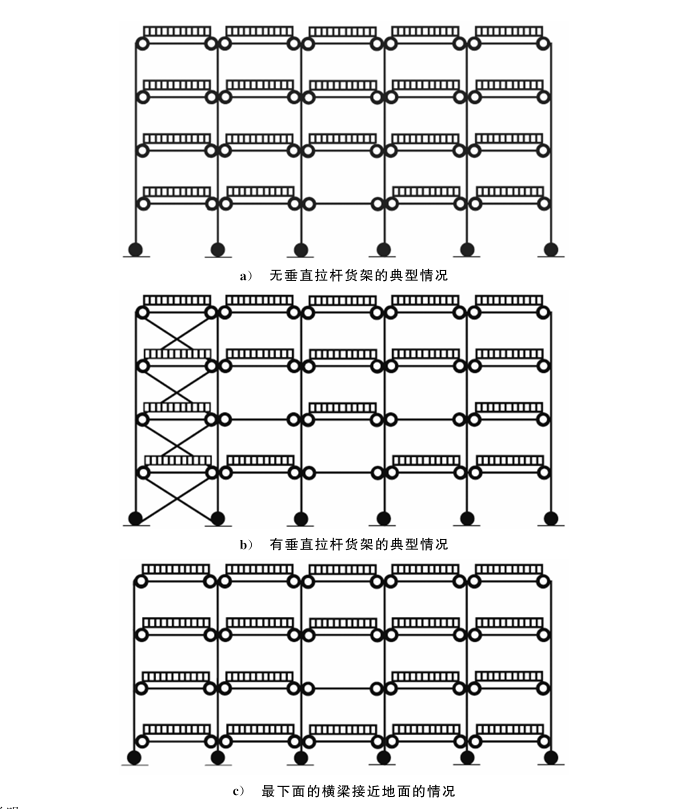
For column design in racking design, two primary loading patterns must be considered:
Pattern (a) : All beams fully loaded except one beam near mid-height of the lowest level (empty)
Pattern (b) : For racks with vertical tie rods, a single-curvature bending pattern must also be considered
Pattern (c) : If the first beam is near ground level, the second-level beam is considered unloaded
H3: Effective Cross-Sectional Area in Racking Design
Column design in racking design relies on the effective cross-sectional area (A<sub>eff</sub>) , which accounts for post-buckling strength of plate elements. Two distinct effective areas are defined in the racking design norma:
Effective cross-sectional area (A<sub>e</sub>) : Considers post-buckling strength without deducting holes
Effective net cross-sectional area (A<sub>en</sub>) : Considers post-buckling strength with holes deducted
These areas may be determined by finite element analysis or through short column testing (see Section 7.3). For A<sub>e</sub>, unperforated specimens are used; for A<sub>en</sub>, perforated specimens representative of actual columns are required.
H3: Buckling Calculation Length in Racking Design
La buckling calculation length (l) in racking design is determined as l = K × L, where L is the length between supports in the relevant buckling mode.
In the rack frame plane:
Generally, K = 1.0, l = h (where h is the beam spacing)
K = 0.9 may be used when all of the following conditions are met:
Single brace connects to both flanges of the column
Brace eccentricity satisfies the requirements
Columns have base plates
The floor is concrete
Perpendicular to the rack frame (with vertical tie rods):
Generally, K = 1.0, l = h
If beam spacing h<sub>p</sub> exceeds h, then l = h<sub>p</sub>
Perpendicular to the rack frame (without vertical tie rods):
Generally, K = 1.7, l = K × h
The K value may also be determined through more detailed calculation considering beam-column joint stiffness (k<sub>b</sub>), base stiffness (k<sub>u</sub>), and structural dimensions
For overall rack frame stability in racking design:
K values depend on load centroid location:
Below H/2: K = 1.1
Below 2H/3: K = 1.6
Above 2H/3: K = 2.0
H2: Beam Design in Racking Design
H3: Load Distribution in Beam Racking Design
Beam loads in racking design are typically treated as uniformly distributed. For cases where this assumption does not hold, the racking design standard provides coefficients (β<sub>m</sub> for moment, β<sub>θ</sub> for rotation, β<sub>a</sub> for deflection) to convert actual load arrangements into equivalent uniformly distributed loads.
H3: Design Moment in Racking Design
When beam-column joint stiffness (k<sub>b</sub>) is determined through testing (Section 7.5), the design moment at mid-span (M<sub>sd</sub>) in racking design is calculated as:
M<sub>sd</sub> = (W<sub>s</sub>L/8)β<sub>m</sub>[1 – (2/3β<sub>b</sub>)/(β<sub>m</sub>(1 + 2EI<sub>b</sub>/(k<sub>c</sub>L)))]
Where k<sub>c</sub> = k<sub>b</sub>/(1 + k<sub>b</sub>h/(3EI<sub>c</sub>))
This formula accounts for the semi-rigid behavior of beam-to-column connections, which significantly influences moment distribution in racking frames. This is a sophisticated aspect of the racking design standard that recognizes the unique connection behavior in cold-formed steel systems.
H3: Beam Deflection in Racking Design
Similarly, the maximum deflection (Δ<sub>max</sub>) in racking design is calculated as:
Δ<sub>max</sub> = (5W<sub>ser</sub>L³/384EI<sub>b</sub>)β<sub>d</sub>[1 – (0.8β<sub>b</sub>)/(β<sub>d</sub>(1 + 2EI<sub>b</sub>/(k<sub>c</sub>L)))]
H2: Base Plate Design in Racking Design
Each column in racking design must be provided with a base plate and a clear anchorage method. The racking design standard provides an approximate design method for axially loaded base plates. For combined axial and bending loads, testing per Section 7.6 is required.
The effective base plate area (A<sub>b</sub>) in racking design assumes uniform pressure distribution over the effective area. The effective width (e) is:
e = t<sub>b</sub>√(f<sub>y</sub>/(3f<sub>c</sub>))
Where:
t<sub>b</sub> = base plate thickness
f<sub>y</sub> = nominal yield strength
f<sub>c</sub> = concrete compressive strength design value = 1.67f<sub>ck</sub>
f<sub>ck</sub> = concrete cylinder compressive strength
For a centrally loaded column with design axial load (N<sub>sd</sub>):
N<sub>sd</sub> = f<sub>c</sub> × A<sub>b</sub>
H2: Anchor Bolt Design in Racking Design
Anchor bolt design in racking design must follow JGJ 145-2013 “Technical specification for post-installed fastenings in concrete structures” or manufacturer-provided design data.
H1: Test Acquisition and Processing Methods in Racking Design
H2: General Testing Requirements in Racking Design
GB/T 39681-2020 places strong emphasis on testing to validate design parameters. The racking design standard recognizes that analytical methods alone cannot fully capture the complex behavior of cold-formed steel racking systems with perforated sections and semi-rigid connections.
Key requirements in the racking design standard include:
Test specimens must use the same steel as the actual rack structure
Specimen cross-sections must be formed identically to production members
Testing equipment must be calibrated and certified by qualified metrology authorities
H2: Material Testing in Racking Design (Section 7.2)
H3: Yield Strength Determination for Racking Design
Actual yield strength (f<sub>t</sub>) is determined through tensile testing per GB/T 228.1, with specimens taken along the rolling direction.
H3: Bend Testing for Racking Design
Bend testing per GB/T 232 verifies material ductility. Specimens undergo 180° bending with a bend radius equal to twice the specimen thickness. The specimen passes if no cracks appear on the exterior of the bend. Minor cracks extending no more than 1mm from the specimen edge are permitted.
H2: Column Effective Cross-Sectional Area Testing (Section 7.3)
La short column test in racking design determines both A<sub>e</sub> and A<sub>en</sub>. Test specimens must:
Have length ≥ 3 × maximum cross-sectional dimension
Include at least 5 regular hole patterns
Be cut perpendicular to the longitudinal axis between perforations
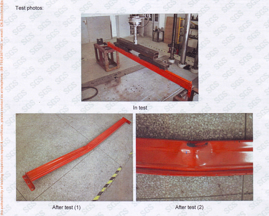
Specimens are mounted between thick (≥30mm) steel plates with a steel ball at each end to apply axial load. The steel ball diameter depends on the expected ultimate load, ranging from 10mm for 50kN to 50mm for 1,250kN.
La characteristic ultimate load (R<sub>k</sub>) in racking design is determined through statistical correction of test results:
R<sub>k</sub> = R<sub>m</sub> – K<sub>s</sub> × S
Where:
S = standard deviation
K<sub>s</sub> = factor depending on number of tests (n ≥ 3)
R<sub>m</sub> = mean corrected ultimate load
The effective cross-sectional area in racking design is then:
A<sub>eff</sub> = R<sub>k</sub> / f<sub>y</sub>
H2: Column Stability Coefficient Testing (Section 7.4)
La stability coefficient (χ) in racking design is determined through rack frame testing. This coefficient represents the reduction factor for column buckling in the along-aisle direction.
Test requirements in the racking design norma:
Use assembled rack frames at the maximum product width
Load applied to only one column (or each column individually)
Support configuration identical to actual product
At least five specimen lengths are required, ranging from a single brace spacing to a length corresponding to λ̄ = 1.5.
The stability coefficient design value in racking design is:
χ = χ<sub>m</sub>(1 – K<sub>s</sub>S)
Where χ<sub>m</sub> is the mean of individual χ<sub>ni</sub> values.
H2: Beam-Column Joint Stiffness Testing (Section 7.5)
This critical test in racking design determines the rotational stiffness (k<sub>b</sub>) of beam-to-column connections.
The test setup in the racking design standard involves:
A short column segment attached to a rigid test frame
A beam loaded at 400mm from the column face
Two displacement transducers to measure rotation
Both left and right connection stiffness values are measured separately, and the average is used for racking design. The moment-rotation curve is plotted and the characteristic failure moment (M<sub>k</sub>) is determined statistically.
The design rotational stiffness in racking design is:
k<sub>ni</sub> ≤ 1.15M<sub>Rd</sub>/θ<sub>Rdi</sub>
Where M<sub>Rd</sub> is the design moment resistance and θ<sub>Rdi</sub> is the rotation at M<sub>Rd</sub>.
H2: Base Stiffness Testing (Section 7.6)
Base stiffness (k<sub>u</sub>) in racking design is determined through a specialized test setup with:
Two column segments at least 4 times the maximum column width
Base plates mounted on concrete blocks matching actual conditions
Two jacks applying loads in orthogonal directions
The base moment (M<sub>b</sub>) and rotation (θ<sub>b</sub>) are calculated from measured displacements.
H1: Overall Combined Racking Unit Testing (Section 8)
H2: Purpose and Setup of Racking Design Testing
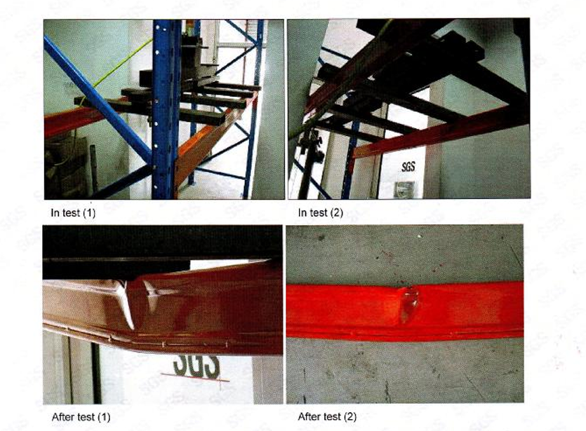
This test in the racking design standard simulates actual operating conditions to determine the racking system’s ultimate capacity and rated load.
The test setup specified in the racking design standard consists of:
At least three rack frames connected by beams over two or more storage levels
Bottom beams and frames matching actual construction
Top beams and frames reinforced to withstand loads exceeding the overall frame failure load
H2: Loading Protocols in Racking Design Testing
Three loading protocols are specified in the racking design norma:
Protocol (a) : Vertical loads at 1.5× design load on each beam level, plus horizontal loads equal to 1.5% of the vertical load at each beam-to-column connection. Loads are then increased incrementally on the top level only until failure.
Protocol (b) : Vertical loads at 1.5× design load on a single pallet position at the bottom level, then incremental loading on the top level as in Protocol (a).
Protocol (c) : Same as Protocol (a), but horizontal loads are applied in the perpendicular direction (within the rack frame plane).
H2: Capacity Determination in Racking Design Testing
La ultimate load in racking design is taken as the minimum failure load from the three protocols. The rated load estas one-half of the ultimate load.
This conservative 2:1 safety factor in the racking design standard provides a substantial margin against unforeseen overloads, material variability, and long-term degradation.
H1: Appendix A—Equivalent Calculation Length Coefficient K in Racking Design
Appendix A of the racking design standard provides methodology for determining the effective length coefficient K for racks without vertical tie rods.
The calculation in racking design involves determining G<sub>A</sub> (at the beam-to-column connection) and G<sub>B</sub> (at the base):
G<sub>A</sub> = [I<sub>c</sub>(1/L<sub>c1</sub> + 1/L<sub>c2</sub>)] / [2(I<sub>b</sub>/L<sub>b</sub>)<sub>red</sub>]
Where (I<sub>b</sub>/L<sub>b</sub>)<sub>red</sub> accounts for semi-rigid connection behavior in racking design:
(I<sub>b</sub>/L<sub>b</sub>)<sub>red</sub> = (I<sub>b</sub>/L<sub>b</sub>) / [1 + 6(EI<sub>b</sub>/(L<sub>b</sub>k<sub>b</sub>))]
For the base in racking design:
(I<sub>f</sub>/L<sub>f</sub>) = k<sub>u</sub>/(6E) (empirical formula for base plates fixed to concrete)
La racking design standard notes that this empirical formula only applies when base plates are directly fixed to concrete floors. For adjustable base plates with no grouting, the base is effectively pinned, and G<sub>B</sub> should be taken as 10.
H1: Appendix B—Width-to-Thickness Ratio Requirements in Racking Design
Appendix B of the racking design standard establishes maximum width-to-thickness ratio (b<sub>p</sub>/t) limits for uniformly compressed plate elements to prevent local buckling.
Por doubly-supported plates (plates supported on both longitudinal edges), limits in the racking design standard range from:
39.5 at 215 MPa to 26 at 500 MPa
Por singly-supported plates (flanges with one free edge), limits in the racking design standard range from:
13 at 215 MPa to 8 at 500 MPa
La racking design standard also specifies minimum lip dimensions for singly-supported plate elements (such as section lips), with lip width-to-thickness ratios ranging from 5.4 to 9.0 depending on the adjacent plate’s b<sub>p</sub>/t ratio.
These provisions in the racking design standard ensure that section elements do not buckle locally before the member reaches its global buckling capacity.
H1: Practical Implications for Warehouse Design and Operation
H2: Impact on New Facility Racking Design
For warehouse operators planning new facilities, GB/T 39681-2020 provides a clear, enforceable framework por racking design. The racking design standard’s requirements for:
Material traceability (steel grades, impact test certificates for cold storage)
Load documentation (comprehensive load combinations)
Testing verification (short column tests, frame tests, connection tests)
Overall unit testing (validating complete systems)
These provisions give owners confidence that their racking systems will perform safely throughout their service life.
H2: Retrofitting and Modification in Racking Design
For existing facilities, the racking design standard provides guidance for:
Evaluating existing racks against current requirements
Modifying rack configurations (changing beam spacing, adding levels)
Upgrading to automated operations (addressing impact loads and horizontal loads from equipment)
H2: Supplier Qualification Through Racking Design Standards
La racking design standard serves as a powerful tool for supplier qualification. Warehouse owners can now require:
Material test certificates (per 7.2)
Short column test results (per 7.3)
Stability coefficient documentation (per 7.4)
Connection stiffness data (per 7.5)
Overall unit test reports (per 8.0)
This standardization in racking design eliminates the “lowest bidder” problem where quality is sacrificed for cost.
H1: Comparison with International Racking Design Standards
H2: Alignment with Global Racking Design Practice
GB/T 39681-2020 aligns with international best practices in racking design while maintaining distinct Chinese requirements:
| Aspect | GB/T 39681-2020 | EN 15512 | ANSI MH 16.1 |
|---|---|---|---|
| Impact load (automated) | 50% | 25% | 25% |
| Horizontal load (imperfections) | 0.4% | Varies | Varies |
| Safety factor (rated load) | 2.0 | Varies | Varies |
| Seismic design | GB 50011 | Eurocode 8 | IBC/ASCE 7 |
The more conservative impact load requirement in the racking design standard (50% vs. 25%) reflects China’s approach to ensuring robust safety margins in automated storage systems.
H2: Harmonization Efforts in Racking Design
La racking design standard’s development involved collaboration with international experts and reference to global standards. This harmonization facilitates:
International trade in racking equipment
Multi-national facility design consistency
Technology transfer and knowledge sharing
H1: Future Developments and Industry Trends in Racking Design
H2: Emerging Technologies Impacting Racking Design
La racking design standard provides a foundation for emerging storage technologies:
Automated Storage and Retrieval Systems (AS/RS) — the racking design standard specifically addresses automated equipment loads
Very Narrow Aisle (VNA) systems — horizontal load provisions in the racking design standard are particularly relevant
Pallet shuttle systems — dynamic loading considerations in racking design
Rack-clad buildings — comprehensive wind, snow, and seismic provisions in the racking design standard
H2: Sustainability Considerations in Racking Design
La racking design standard supports sustainability through:
Material efficiency — enabling lighter sections through accurate racking design
Pli longa servodaŭro — through proper racking design and testing
Reusability — standardized components and connections in racking design
Conclusion
GB/T 39681-2020 “Racking design code for steel static storage systems” represents a milestone achievement in Chinese storage equipment standardization. By establishing comprehensive requirements for materials, loads, design methodologies, and testing protocols, the racking design standard provides the technical foundation for safe, reliable, and efficient warehouse racking systems.
For design engineers, the racking design standard offers clear analytical frameworks for calculating member capacities, connection stiffness, and overall system performance. For warehouse operators, it provides assurance that properly designed and tested racking systems will safely support their operations. For the industry as a whole, it promotes quality, innovation, and international competitiveness.
As warehouse automation accelerates and storage densities increase, the principles embedded in GB/T 39681-2020 will become increasingly critical. The racking design standard’s emphasis on testing—particularly for connections, stability coefficients, and overall system performance—recognizes that analytical methods alone cannot fully capture the complex behavior of cold-formed steel racking systems with perforated sections and semi-rigid connections.
La racking design standard has been instrumental in addressing the technological lag of previous industry guidelines, combining modern lightweight high-strength steel applications with plug-in installation techniques. Through unified racking design criteria for cold-formed and hot-rolled steel static storage systems, the standard has effectively curbed quality issues arising from low-price competition while enhancing product safety performance and market competitiveness.
We strongly recommend that all stakeholders in the warehouse storage industry—from designers and manufacturers to owners and operators—thoroughly familiarize themselves with the requirements of GB/T 39681-2020. The investment in understanding and implementing this racking design standard will pay dividends in safety, performance, and long-term value.
Oftaj demandoj
Q1: Does GB/T 39681-2020 apply to all types of warehouse racking, or only automated systems?
GB/T 39681-2020 applies to steel static storage systems made from cold-formed or hot-rolled steel components, regardless of whether the system is automated or manually operated. The racking design standard specifically addresses both automated equipment (with 50% impact load) and manual operations (with 100% impact load). However, it does not apply to racking systems primarily subjected to dynamic loads or systems made from materials other than steel.
Q2: What is the difference between “effective cross-sectional area” and “effective net cross-sectional area” in racking design?
Effective cross-sectional area (A<sub>e</sub>) considers the post-buckling strength of plate elements but does not deduct holes (such as perforations in columns). Effective net cross-sectional area (A<sub>en</sub>) also considers post-buckling strength but deducts holes. This distinction is important because perforated columns—common in racking systems—have reduced cross-sectional area at hole locations, which affects both strength and stability. A<sub>e</sub> is determined using unperforated specimens, while A<sub>en</sub> requires perforated specimens.
Q3: How is the horizontal load from rack imperfections determined under this racking design standard?
Horizontal loads from imperfections, installation deviations, and load eccentricities are taken as 0.4% of the sum of dead load and maximum live load transmitted to each beam-to-column connection. This load must be applied in both longitudinal and transverse directions at beam-to-column connection nodes. The racking design standard notes that this 0.4% value accounts for initial curvature from manufacturing and transportation, installation deviations, and load eccentricities.
Q4: What testing is required to validate a new racking system design under GB/T 39681-2020?
La racking design standard requires multiple levels of testing: (1) material tensile and bend testing per 7.2, (2) short column testing to determine effective cross-sectional area per 7.3, (3) rack frame testing to determine stability coefficients per 7.4, (4) beam-column connection stiffness testing per 7.5, (5) base stiffness testing per 7.6, and (6) overall combined racking unit testing per Section 8. The overall unit test is particularly important as it validates the complete system’s performance under realistic loading conditions.
Q5: Can I use the effective length coefficient K = 1.7 for all racks without vertical tie rods?
La racking design standard specifies that K = 1.7 estas general approximation for racks without vertical tie rods. However, a more accurate K value can be determined by considering beam-column joint stiffness (k<sub>b</sub>), base stiffness (k<sub>u</sub>), and structural dimensions, following the methodology in Appendix A. For critical applications or where optimization is important (such as reducing column sizes), we strongly recommend the more detailed calculation approach rather than relying on the general approximation.
Geelyracks specializes in the production of warehouse racks and is a global rack customization expert: https://geelyracks.com/
Se vi bezonas perfektajn CAD-desegnaĵojn kaj ofertojn por magazenaj bretoj, Bonvolu kontakti nin.. Ni povas provizi al vi senpagajn servojn pri planado kaj projektado de magazenaj bretoj kaj prezproponojn. Nia retpoŝtadreso estas: jili@geelyracks.com