📐 "First 50 Enterprise Queries Get Custom 3D Warehouse Design" Plan















Industrial Rack Design Calculation: A Comprehensive Technical Guide to GB/T 28576—2012
Abstract: Industrial rack systems constitute the foundational infrastructure of modern logistics and warehousing operations worldwide. The structural integrity of any industrial rack depends entirely on rigorous design calculations that must account for complex load combinations, seismic events, operational stresses, and long-term fatigue considerations.
This comprehensive technical guide explores the Chinese national standard GB/T 28576—2012 “Calculation of Industrial Rack Design,” which establishes the fundamental framework for designing assembled industrial racks including AS/RS racks, very narrow aisle pallet racks, and conventional pallet racks. This article examines the standard’s structural classifications, calculation models, load combinations, and verification methodologies for strength, stiffness, and stability.
Drawing on decades of industry expertise and real-world engineering applications, this guide provides warehouse engineers, logistics professionals, facility managers, and procurement specialists with the technical knowledge needed to ensure any industrial rack system meets safety requirements while optimizing material usage and operational efficiency. The principles outlined herein apply whether one is designing a new industrial rack installation, evaluating an existing industrial rack for capacity upgrades, or specifying an industrial rack for a new warehouse facility.
H1: Understanding Industrial Rack Design Calculation Under GB/T 28576—2012
The design and calculation of industrial storage racks represent one of the most critical engineering disciplines in modern logistics infrastructure. GB/T 28576—2012, officially titled “Calculation of Industrial Rack Design,” serves as the foundational Chinese national standard governing how assembled industrial racks must be engineered for safety, durability, and performance. Anyone involved in warehouse operations, from facility managers to procurement specialists, must understand that a properly designed industrial rack is not merely a storage solution—it is a sophisticated structural system that demands meticulous engineering analysis.
The standard’s development was driven by a pressing industry need that should concern anyone involved in warehouse operations. As the logistics sector experienced explosive growth—with assembled industrial racks growing at over 25% annually and the national industrial rack industry exceeding 3 billion RMB in output by 2009—design calculation techniques lagged dangerously behind. The consequences were severe and sobering: industrial rack collapse incidents caused over 100 million RMB in direct economic losses and resulted in significant casualties. The 2008 Wenchuan earthquake further underscored the urgent need for standardized seismic design requirements for every industrial rack installed in seismic zones.
GB/T 28576—2012 addresses these challenges by establishing a probability-based limit state design methodology with partial coefficient design expressions. It applies specifically to assembled industrial racks used in automated storage and retrieval system (AS/RS) racks, very narrow aisle pallet racks, and conventional pallet racks, though other industrial rack types may reference it for guidance【4†L3-L5】. The standard’s scope deliberately focuses on pallet-based storage systems, including those using totes and unit-load storage, while excluding shelving, flow racks, and retail display systems where loads are typically under 100 kg per level and heights remain below 2,200 mm. This focus ensures that the standard addresses the most critical industrial rack applications where failure would have the most severe consequences.
What makes this industrial rack standard particularly significant is its mandatory requirement for finite element method (FEM) analysis in specific scenarios【11†L8-L10】. For industrial racks exceeding 6 meters in height, all AS/RS racks, and all corbel pallet racks, overall strength and stability analysis must employ FEM—a requirement that represents a major advancement over earlier design practices that often relied on simplified hand calculations. This mandate reflects the understanding that modern industrial rack systems have become too complex and too tall for simplified analytical methods to ensure safety.
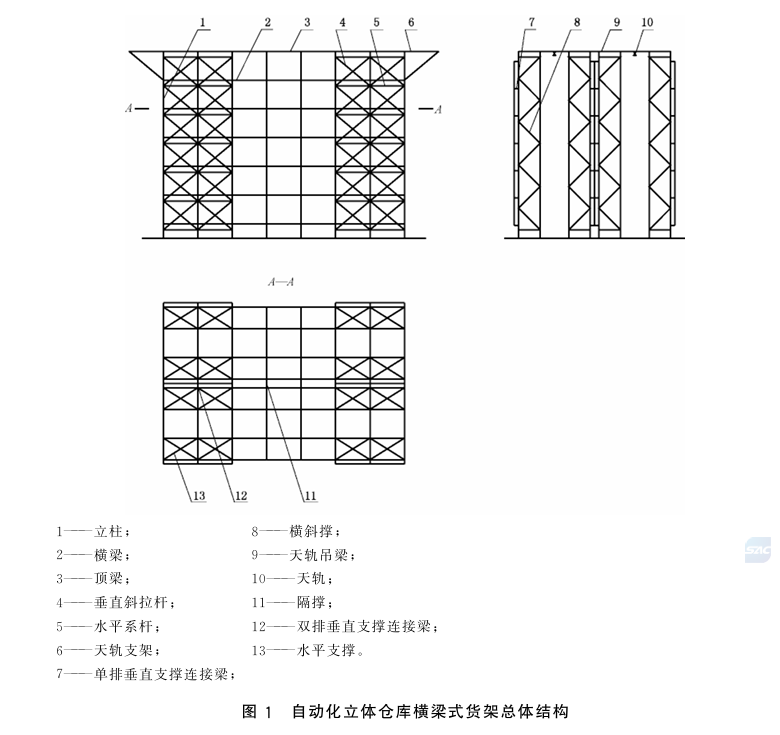
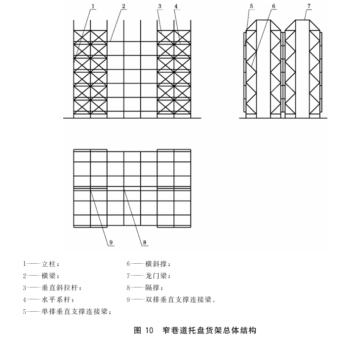
H2: Industrial Rack Structural Classifications and Configurations
Understanding the structural anatomy of industrial racks is essential before any calculation can begin. GB/T 28576—2012 categorizes industrial racks into three primary types, each with distinct structural configurations and calculation requirements. This classification system helps engineers and procurement specialists select the appropriate industrial rack type for specific warehouse applications.
H3: Automated Storage and Retrieval System (AS/RS) Industrial Racks
AS/RS industrial racks represent the most sophisticated category, designed specifically for automated warehouses where stacker cranes operate within industrial rack aisles【4†L7-L8】. These industrial rack structures consist of upright frames (立柱片), beams (or cantilever arms), top beams, horizontal tie bars, vertical diagonal braces, vertical support connecting beams, horizontal bracing, cross-diagonal bracing, spacer bracing, crane rails, and rail hanger beams【5†L4-L7】. Every component of this industrial rack type plays a critical role in maintaining structural integrity under automated loading conditions.
The upright frame—the primary load-bearing component of any AS/RS industrial rack—comprises two upright columns connected by diagonal bracing in V-type, N-type, or K-type configurations【5†L11-L13】. The choice of bracing pattern significantly influences the industrial rack’s stiffness and load-carrying capacity. Vertical support structures in AS/RS industrial racks come in three variants: X-type rigid, X-type flexible, and Z-type rigid, each pair spanning either 1-2 levels or 1-2 columns【6†L4-L6】. Horizontal support structures similarly offer X-type, K-type, and V-type arrangements, with longitudinal placement corresponding to vertical support positions【6†L12-L14】.
For corbel-type AS/RS industrial racks, the structural composition expands to include cantilever beams, continuous beams, and corbel beams in addition to the standard components, with vertical supports required across the entire length of the industrial rack【7†L7-L12】. This industrial rack configuration is particularly suitable for applications requiring dense storage of irregularly shaped items.
H3: Very Narrow Aisle (VNA) Industrial Pallet Racks
Very narrow aisle industrial pallet racks accommodate turret trucks or wire-guided stackers operating in aisles significantly narrower than conventional forklift aisles【9†L4-L6】. The industrial rack structural configuration includes uprights, beams, vertical supports, vertical support connecting beams, cross-diagonal bracing, spacer bracing, and gantry beams. While uprights, cross-diagonal bracing, beams, and gantry beams are mandatory components of this industrial rack type, other components remain optional【9†L8-L10】.
A critical design consideration emerges when VNA industrial racks exceed six levels: vertical supports should be added every 5-6 columns, positioned at both ends and the middle of the industrial rack in the longitudinal direction【9†L16-L18】. Similarly, horizontal supports should increase under the same conditions, with placement aligning with vertical supports and spacing at every level or every 1-2 levels vertically【9†L20-L22】. Gantry beam structures—essential for lateral stability in tall industrial racks—come in full-height and stepped-height configurations【10†L3-L5】.
H3: Conventional Industrial Pallet Racks
Conventional industrial pallet racks represent the most common warehouse storage solution, operated by standard counterbalanced forklifts【10†L9-L11】. The industrial rack structural composition includes uprights, beams, vertical supports, vertical support connecting beams, cross-diagonal bracing, and spacer bracing. Only uprights, cross-diagonal bracing, and beams are mandatory components of this industrial rack type; all other components remain optional【10†L11-L13】.
The same vertical and horizontal support rules apply when conventional industrial racks exceed six levels【11†L3-L5】. Additionally, when the upright frame height-to-width ratio reaches or exceeds 8:1, gantry beams become recommended for the industrial rack【11†L7-L8】. This recommendation reflects the understanding that tall, narrow industrial rack configurations are particularly susceptible to lateral instability.
H2: Industrial Rack Calculation Principles and Modeling Methodology
GB/T 28576—2012 establishes a rigorous probabilistic limit state design framework that distinguishes between ultimate and serviceability limit states. Anyone responsible for industrial rack design must understand these fundamental principles.
H3: Core Industrial Rack Calculation Principles
The industrial rack standard mandates two distinct calculation approaches depending on the analysis objective【11†L3-L5】. For overall strength and stability analysis of any industrial rack, the ultimate limit state method must be employed, using design loads and design strength values. For stiffness analysis of an industrial rack, the serviceability limit state method applies, using standard loads and deformation limits【11†L5-L7】.
Local and individual component calculations for an industrial rack may utilize mechanics of materials, structural mechanics, elastic-plastic mechanics, or finite element methods【11†L8-L9】. However, overall industrial rack strength and stability analysis should preferably employ FEM, with mandatory FEM application for specific industrial rack types【11†L10-L12】:
Industrial racks exceeding 6 meters in height (conventional and VNA pallet racks)
All AS/RS industrial racks
All corbel pallet industrial racks
This represents a significant departure from earlier practices where simplified analytical methods often sufficed for industrial rack design. The standard’s drafters recognized that as industrial rack systems grow taller and more complex, the interactions between components, load paths, and failure modes demand the sophisticated computational capabilities that FEM provides.
H3: Building the Industrial Rack Calculation Model
The industrial rack standard establishes an absolute coordinate system (xOz, yOz, xOy planes) as the reference framework【11†L14】. When performing overall FEM analysis, industrial racks should be simplified into three-dimensional spatial frame models, with natural connection points serving as nodes and components between adjacent nodes forming elements【11†L16-L18】.
Industrial rack model simplification rules address the practical reality that full industrial racks may contain hundreds or thousands of bays【11†L20-L24】. The standard specifies:
Number of rows: For industrial racks with aisle connections, even numbers of rows should be selected; for industrial racks without aisle connections, odd numbers suffice
Number of columns: Must include at least 6 columns with at least two non-adjacent vertical support columns
Number of levels: Must reflect actual industrial rack levels—no simplification permitted
Component simplification categorizes structural members as either beam elements or truss elements【12†L5-L8】. Uprights, beams (including load beams and top beams), cantilever beams, corbel beams, vertical support connecting beams, rail hanger beams, and crane rails in an industrial rack qualify as beam elements. Cross-diagonal bracing, horizontal tie bars, vertical diagonal braces, and horizontal supports function as truss elements.
H3: Industrial Rack Constraints and Boundary Conditions
The industrial rack standard meticulously defines constraint types—rigid connections, hinged connections, and semi-rigid connections—for each component connection, with specific conditions based on bolt configurations【12†L11-L13】【13†L4-L27】.
Upright-to-floor connections in an industrial rack vary by anchoring method:
Single-bolt connections: semi-rigid in all directions
Double-bolt connections: semi-rigid in xOz, rigid in yOz and xOy
Embedded plate connections: rigid in all directions
Upright-to-beam connections in an industrial rack follow semi-rigid in xOz, rigid in yOz and xOy. Upright-to-cantilever beam connections follow the same pattern. Upright-to-diagonal bracing connections vary: double-hole connections are rigid in all directions, while single-hole connections are rigid in xOz and semi-rigid in yOz.
These detailed connection specifications reflect the industrial rack standard’s recognition that joint behavior significantly influences overall industrial rack performance—a factor often overlooked in simpler design approaches. Proper modeling of these connections is essential for accurate industrial rack analysis.
H2: Load Types and Load Combinations for Industrial Racks
Industrial racks experience a complex array of loads throughout their service life. GB/T 28576—2012 categorizes these into five distinct types and defines how they must be combined for different calculation scenarios. Understanding these loads is essential for anyone specifying or designing an industrial rack.
H3: Dead Loads on Industrial Racks (恒荷载)
Dead loads on an industrial rack comprise the self-weight of the entire industrial rack structure, including all beams, uprights, and other components【13†L31-L32】. While seemingly straightforward, accurate dead load calculation for an industrial rack requires detailed material takeoffs and consideration of all structural members, connections, and accessories. Engineers must account for every component of the industrial rack, from the heaviest beams to the smallest connection plates.
H3: Live Loads on Industrial Racks (活荷载)
Live loads on an industrial rack represent the weight of goods and pallets stored on the industrial rack, considered on a level-by-level basis【13†L34-L35】. The industrial rack standard requires considering actual load conditions, recognizing that different levels of an industrial rack may carry different loads depending on storage strategies and operational requirements. This level-by-level approach ensures that each portion of the industrial rack is properly designed for its specific loading condition.
H3: Vertical Impact Loads on Industrial Racks (竖向冲击荷载)
Vertical impact loads on an industrial rack arise from material handling equipment placing loads onto beams or cantilever arms【13†L37-L39】. The industrial rack standard specifies that impact loads equal 50% of the static design load of a single storage unit when mechanical equipment is used for placement.
When calculating an industrial rack under ultimate limit state conditions, impact loads must be considered at the most unfavorable position, and the resulting stresses must not exceed design strength values【13†L40-L41】. However, when calculating industrial rack beam deflection, impact loads need not be considered—a distinction that reflects the different nature of strength and serviceability requirements【13†L42】. This nuanced approach ensures that industrial rack designs are neither over-conservative nor under-designed.
H3: Horizontal Loads on Industrial Racks (水平荷载)
Horizontal loads on an industrial rack originate from multiple sources: initial curvature of structural members, installation deviations, load eccentricity, and minor collisions from material handling equipment【13†L44-L45】. The industrial rack standard specifies that horizontal loads should act at beam-to-upright connection nodes in both x and y directions, with magnitude equal to 1.5% of the total dead load plus maximum live load transmitted to that node by the beam【13†L46-L48】.
For AS/RS industrial racks, additional horizontal forces arise from stacker crane fork extension under full load conditions【13†L49-L51】. The horizontal force F on an AS/RS industrial rack is calculated as:
F = k × G × (l / h)
Where:
k = weighting coefficient (1.2–1.5)
G = rated load of the storage unit (kg)
l = fork extension length (mm)
h = stacker crane height (mm)
H3: Seismic Loads on Industrial Racks (地震荷载)
Seismic loads on an industrial rack consider only horizontal seismic effects (longitudinal waves in x and y directions), with vertical seismic effects explicitly excluded【13†L53-L54】. Seismic load calculation for an industrial rack follows the methodology in Appendix A of the standard, which references GB 50011—2010 “Code for Seismic Design of Buildings”【4†L9】.
The industrial rack standard defines the horizontal seismic action FE as【18†L17-L18】:
FE = α₁ × Geq
Where:
α₁ = horizontal seismic influence coefficient corresponding to the industrial rack’s fundamental natural period
Geq = equivalent total weight of the industrial rack structure (0.85 × total gravity load representative value)
The horizontal seismic influence coefficient α₁ for an industrial rack varies based on the industrial rack’s natural period T【18†L30-L38】:
When T ≤ 0.1s: α₁ = (0.45 + 5.5T) × αmax
When 0.1 < T ≤ Tg: α₁ = αmax
When Tg < T ≤ 3s: α₁ = (Tg/T)^0.9 × αmax
Tg represents the characteristic period based on site category and seismic design group, while αmax represents the maximum horizontal seismic influence coefficient based on seismic intensity【18†L43-L49】【19†L3-L6】.
H3: Industrial Rack Load Combination Scenarios
The industrial rack standard defines three primary calculation工况 (load cases)【14†L3-L15】:
1. Normal Operating Condition (正常工况)
The industrial rack’s normal loaded state, considering dead loads, live loads, vertical impact loads, and horizontal loads in both x and y directions. This scenario drives strength, deformation, and stability verification for the industrial rack.
2. Seismic Condition (地震工况)
The industrial rack’s seismic loading state, considering dead loads, live loads (at 80% fill rate), and seismic loads in both x and y directions. Under this condition, only strength verification is required for the industrial rack—deformation and stability checks are unnecessary.
3. Eccentric Loading Condition (偏载工况)
The industrial rack’s state under asymmetric loading conditions, considering dead loads and unbalanced live loads. Both strength and stability verification apply to the industrial rack under this condition.
Industrial rack load combination expressions follow standardized formats【17†L4-L18】【18†L7-L14】:
Combination 1 (Dead + Live): γG·CG·Gk + γQ·CQ·Qk
Combination 2 (Dead + Live + Impact): γG·CG·Gk + γQ(CQ·Qk + CQ1·Q1k)
Combination 3 (Dead + Live + Horizontal): γG·CG·Gk + γQ(CQ·Qk + CQ2·Q2k)
Combination 4 (Dead + Live + Seismic): γG·CG·GE + γE·CE·FE
Partial load factors for industrial rack design differ between ultimate and serviceability limit states【15†L10-L17】:
| Load Type | Ultimate Limit State | Serviceability Limit State |
|---|---|---|
| Dead Load | 1.2 | 1.0 |
| Live Load | 1.4 | 1.0 |
| Vertical Impact | 1.4 | 1.0 |
| Horizontal Load | 1.4 | 1.0 |
| Seismic Load | 1.3 | 1.0 |
H2: Industrial Rack Strength Verification (强度校核)
Strength verification ensures that industrial rack components can withstand applied loads without yielding or fracturing. GB/T 28576—2012 establishes specific design strength values and calculation methods for different industrial rack component types【15†L19-L21】.
H3: Industrial Rack Design Strength Values
The industrial rack standard adopts design strength values from GB 50018—2002 “Technical Code of Cold-formed Thin-wall Steel Structures”【15†L23-L25】:
| Steel Grade | Tension, Compression, Bending (f) | Shear (fv) | Bearing (fce) |
|---|---|---|---|
| Q235 Steel | 205 MPa | 120 MPa | 310 MPa |
| Q345 Steel | 300 MPa | 175 MPa | 400 MPa |
For cold-formed steel sections where the full cross-section is effective, the industrial rack standard permits using strength design values accounting for cold-forming effects, calculated per GB 50018—2002 Appendix C【15†L26-L28】.
Seismic strength design values for an industrial rack incorporate an adjustment factor【15†L30-L33】:
fE = f / γRE
Where γRE (seismic strength adjustment factor) equals 0.80 for industrial rack beams and columns, and 0.90 for bracing and connections.
H3: Component-Specific Industrial Rack Strength Calculations
Different industrial rack components experience fundamentally different stress states, requiring tailored calculation approaches【15†L35-L37】【20†L4-L30】:
Uprights (立柱) in an industrial rack function as beam-columns under combined axial compression and bending. The stress calculation follows【20†L5-L7】:
σ = N/Aen ± Mx/Wenx ± My/Weny ≤ f
Where N is axial force, Aen is effective net cross-sectional area, Mx and My are bending moments about principal axes, and Wenx and Weny are effective net section moduli.
Beams (横梁) in an industrial rack function as flexural members【20†L9-L19】. When loads pass through the shear center parallel to the principal axis:
σ = Mmax/Wmax ≤ f
τ = Vmax·S/(I·t) ≤ fv
Where Mmax is maximum bending moment, Wmax is section modulus, Vmax is maximum shear force, S is first moment of area, I is moment of inertia, and t is web thickness.
When loads deviate from the shear center, additional torsional stresses must be considered for the industrial rack beam.
Bracing members (支撑类构件) in an industrial rack function as axially loaded members (tension or compression)【20†L32-L34】:
σ = N/Aen ≤ f
H2: Industrial Rack Stiffness Verification (刚度校核)
Stiffness verification ensures that industrial rack deformations remain within acceptable limits, preventing excessive deflections that could impair functionality or create instability【16†L3-L6】.
H3: Industrial Rack Deformation Calculation
Industrial rack deformation must be calculated using the serviceability limit state approach, considering the most unfavorable load combinations from Table 3 of the standard【16†L3-L4】. All partial load factors equal 1.0 under serviceability limit state conditions for industrial rack design【16†L5-L6】.
H3: Industrial Rack Deformation Limits
The industrial rack standard establishes maximum deformation limits for three deformation types—node displacements, beam maximum displacements, and cantilever beam maximum displacements—with values varying by industrial rack type【16†L8-L10】【16†L14-L21】:
| Deformation Location | AS/RS Industrial Rack (mm) | VNA Industrial Rack (mm) | Conventional Industrial Rack (mm) |
|---|---|---|---|
| Node max x-direction | 10 | 15 | 15 |
| Node max y-direction | 10 | 15 | 15 |
| Node max z-direction | 10 | 15 | 15 |
| Beam max z-deflection | Span/300 (max 10mm) | Span/200 (max 15mm) | Span/200 (max 15mm) |
| Cantilever beam max z-deflection | Span/200 | Span/150 | Span/100 |
These limits reflect the tighter tolerances required for automated industrial rack systems where precise positioning is essential for stacker crane operations.
H2: Industrial Rack Stability Verification (稳定性校核)
Stability verification addresses the risk of buckling—sudden, often catastrophic failure under compressive loads that remains the most common cause of industrial rack collapse【16†L23-L25】.
H3: Component-Specific Industrial Rack Stability Calculations
The stability calculation methodology for an industrial rack mirrors the strength calculation framework but incorporates stability coefficients that account for member slenderness and end conditions【16†L27-L29】【22†L4-L37】.
Uprights (beam-columns) in an industrial rack require stability verification in both the plane of bending and out of the plane【22†L5-L7】. When bending acts in the symmetry plane:
N/(φ·Ae) + βm·M / [(1 – N/N’E)·φ·We] ≤ f
Where φ is the stability coefficient for axially loaded compression members, βm is the equivalent moment coefficient, and N’E accounts for Euler buckling effects.
When bending causes compression on the shear-center side of the industrial rack upright:
|N/Ae – βmy·My / [(1 – N/N’Ey)·W’e]| ≤ f
When bending acts in a non-symmetry principal plane of the industrial rack upright, both in-plane and out-of-plane stability must be verified with additional terms accounting for bi-moment effects.
Industrial rack beams require lateral-torsional buckling verification【23†L5-L9】:
Mmax/(φbx·Wex) ≤ f
Where φbx is the overall stability coefficient for flexural members.
Industrial rack bracing members require compression buckling verification【24†L4-L7】:
N/(φ·Ae) ≤ f
H3: Seismic Exemption for Industrial Rack Stability
The industrial rack standard explicitly exempts stability verification under seismic conditions, recognizing that seismic demands are primarily strength-based and that stability failures typically manifest under sustained or static loading【16†L29-L30】.
H2: Industry Implications and Best Practices for Industrial Rack Design
The implementation of GB/T 28576—2012 has transformed industrial rack design practices across China’s logistics sector and offers valuable lessons for industrial rack designers worldwide.
H3: The Finite Element Mandate for Industrial Racks
The industrial rack standard’s requirement for FEM analysis in tall and automated industrial racks represents a paradigm shift【11†L8-L12】. However, industry experts caution against treating FEM as a black-box solution for industrial rack design. Proper model building, boundary condition definition, and load application remain critical to obtaining meaningful results for any industrial rack. The standard’s drafters emphasized that FEM should complement—not replace—engineering judgment grounded in mechanics fundamentals.
H3: Vertical Bracing—The Overlooked Industrial Rack Essential
Industry experts have highlighted that vertical bracing—required by the industrial rack standard as an essential structural element—is frequently omitted in commercial industrial rack installations, creating significant (safety hazards), particularly under seismic loading. The industrial rack standard’s clear identification of vertical bracing as mandatory (except for spacer bracing, which remains optional) addresses this dangerous practice【5†L5-L7】.
H3: Industrial Rack Model Simplification in Practice
For practical FEM implementation of an industrial rack, the standard’s simplification rules provide essential guidance【11†L20-L24】:
For independent pallet industrial racks without aisle connections, a single row suffices for analysis
For AS/RS industrial racks or industrial racks with aisle connections, two rows better represent actual conditions
Column direction may be simplified but must include at least 6 columns (7 rack frames) with two complete vertical brace groups
Level direction must never be simplified—actual level count must be modeled for the industrial rack
H3: Industrial Rack Connection Modeling
The industrial rack standard’s detailed connection specifications reflect a critical insight: connection behavior significantly influences overall industrial rack performance【12†L11-L13】【13†L4-L27】. Semi-rigid connections—particularly common in bolted industrial rack systems—cannot be modeled as either perfectly rigid or perfectly pinned without introducing significant error. The industrial rack standard’s three-tier connection classification (rigid, hinged, semi-rigid) provides a practical framework for accurate industrial rack modeling.
H2: Comparison of Industrial Rack Standards Across Jurisdictions
GB/T 28576—2012 aligns with international best practices while reflecting Chinese-specific design conditions for industrial racks【25†L3-L8】. The industrial rack standard’s references include:
ANSI MH16.1:2004 “Specification for the Design, Testing and Utilization of Industrial Steel Storage Racks” (USA)—the primary industrial rack standard in North America【25†L3】
FEM 10.2.02 “The Design of Static Steel Pallet Racking” (Europe)—the leading industrial rack standard in European markets【25†L4】
JIS B 8942:2004 “Automated Storage and Retrieval System—General Specifications” (Japan)—the Japanese industrial rack standard for automated systems【25†L5】
CECS 23:90 “Code for Design of Steel Rack Structures” (China)—the predecessor industrial rack standard in China【25†L6】
The 1.5% horizontal load factor for initial imperfections and minor impacts in GB/T 28576—2012 represents a conservative approach compared to some international industrial rack standards that use lower values (e.g., 0.4% in some specifications)【13†L46-L48】. This conservatism reflects the industrial rack standard’s emphasis on safety and its recognition of the variable quality of installation practices.
H2: Industrial Rack Procurement Considerations
For procurement specialists and facility managers specifying an industrial rack, understanding the design calculation requirements is essential for making informed purchasing decisions.
H3: Certifications and Compliance for Industrial Racks
When procuring an industrial rack, buyers should request documentation demonstrating compliance with GB/T 28576—2012 or equivalent international industrial rack standards. This documentation should include:
Design calculation reports for the industrial rack
FEM analysis results (for industrial racks where required)
Material test certificates
Connection test reports
Load capacity charts for the industrial rack
H3: Industrial Rack Load Capacity Verification
Every industrial rack should be clearly marked with its rated load capacity per level and per bay. Procurement specifications should require that the industrial rack supplier provide load capacity documentation based on the design calculation methodology specified in GB/T 28576—2012.
H3: Installation Quality and Industrial Rack Safety
The best-designed industrial rack will fail if improperly installed. Procurement specifications should include requirements for:
Certified industrial rack installation contractors
Installation verification procedures
Post-installation load testing of the industrial rack
Regular inspection and maintenance programs for the industrial rack
H2: Future Trends in Industrial Rack Design
The field of industrial rack design continues to evolve, driven by advances in materials, computational methods, and operational requirements.
H3: Advanced Materials for Industrial Racks
High-strength steels and advanced coatings are enabling industrial rack designers to achieve greater heights with less material. These developments require updated design calculation methods that account for the unique properties of these advanced materials in industrial rack applications.
H3: Digital Twins for Industrial Rack Management
Digital twin technology—creating virtual replicas of physical industrial racks—is emerging as a powerful tool for industrial rack management. These digital twins enable real-time monitoring of industrial rack performance and predictive maintenance, extending industrial rack service life and improving safety.
H3: Automated Industrial Rack Inspection
Drones and robotic inspection systems are being developed for automated industrial rack inspection, detecting damage, corrosion, and deformation that might compromise industrial rack safety. These technologies complement the design calculation methodologies established in GB/T 28576—2012.
Conclusion
GB/T 28576—2012 “Calculation of Industrial Rack Design” stands as an essential technical document that has fundamentally improved the safety and reliability of industrial rack systems throughout China and offers valuable guidance for industrial rack designers worldwide. By establishing a rigorous probabilistic limit state design framework, mandating finite element analysis for critical industrial rack applications, and providing detailed guidance on load combinations, strength verification, stiffness verification, and stability verification, the industrial rack standard equips engineers with the tools needed to design industrial racks that withstand operational demands while optimizing material usage.
The industrial rack standard’s comprehensive treatment of structural configurations—from AS/RS industrial racks to conventional pallet industrial racks—ensures applicability across the full spectrum of warehousing applications【4†L3-L5】【5†L4-L7】【9†L4-L6】【10†L9-L11】. Its detailed specification of connection behaviors, load combinations, and deformation limits for industrial racks reflects decades of accumulated industry knowledge and addresses the real-world failure modes that have historically compromised industrial rack safety.
For warehouse operators, logistics professionals, facility managers, and procurement specialists, understanding and applying GB/T 28576—2012 is not merely a regulatory compliance exercise—it is a fundamental responsibility that directly impacts worker safety, operational continuity, and business sustainability. As industrial rack systems continue growing taller and more automated, the industrial rack standard’s emphasis on rigorous calculation methodologies will only grow in importance.
The tragic history of industrial rack collapses—causing over 100 million RMB in losses and countless injuries—underscores why this industrial rack standard matters. Proper design calculation, executed according to the principles established in GB/T 28576—2012, represents the most effective defense against these catastrophic failures. Every industrial rack installed in any facility represents a significant investment and a long-term commitment to safe, efficient operations. Ensuring that this industrial rack is properly designed, calculated, and verified according to established standards is not just good engineering practice—it is essential to protecting lives, assets, and business continuity.
H2: Frequently Asked Questions
H3: What types of industrial racks are covered by GB/T 28576—2012?
The industrial rack standard covers assembled industrial racks including automated storage and retrieval system (AS/RS) racks, very narrow aisle pallet racks, and conventional pallet racks【4†L3-L5】. Other industrial rack types may reference the standard for guidance, though shelving, flow racks, and retail display systems with low loads (typically under 100 kg per level) and low heights (under 2,200 mm) are not explicitly addressed.
H3: When is finite element method (FEM) analysis mandatory for an industrial rack under the standard?
FEM analysis is mandatory for an industrial rack in the following cases: industrial racks exceeding 6 meters in height (conventional and VNA pallet racks), all AS/RS industrial racks, and all corbel pallet industrial racks【11†L10-L12】. For other industrial racks, FEM is recommended but not required, though local and individual component calculations may use simpler analytical methods.
H3: How is the horizontal load from industrial rack imperfections calculated?
Horizontal loads on an industrial rack caused by initial curvature, installation deviations, load eccentricity, and minor equipment collisions are taken as 1.5% of the total dead load plus maximum live load transmitted to the beam-to-upright connection node【13†L46-L48】. This industrial rack load acts at connection nodes in both x and y directions.
H3: What deformation limits apply to AS/RS industrial rack beams?
For AS/RS industrial rack beams, the maximum z-direction deflection (deflection) is limited to span/300, with an absolute maximum of 10 mm【16†L17-L21】. Node displacements in all directions for an AS/RS industrial rack are limited to 10 mm. These tighter tolerances reflect the precise positioning requirements of automated stacker crane operations.
H3: Does the industrial rack standard require stability verification under seismic conditions?
No. Under seismic conditions, the industrial rack standard requires only strength verification【16†L29-L30】. Stability verification is explicitly exempted for seismic (load cases), as seismic demands are primarily strength-based and stability failures typically manifest under sustained or static loading on the industrial rack.
Geelyracks specializes in the production of warehouse racks and is a global rack customization expert: https://geelyracks.com/
If you require perfect CAD drawings and quotes for warehouse racking, please contact us. We can provide you with free warehouse racking planning and design services and quotes. Our email address is: jili@geelyracks.com