📐 "Le prime 50 richieste aziendali ricevono un design personalizzato del magazzino 3D". Piano















The Complete Guide to Rack Structure Design in High-Bay Warehouses: Tolerances, Deformations, and Clearances According to FEM 9.831
Executive Summary
In the highly automated world of modern logistics, the rack structure serves as the backbone of every high-bay warehouse. Yet the success of any automated storage and retrieval system hinges on a single, often overlooked discipline: the precise calculation of tolerances, deformations, and clearances that govern how the rack structure interacts with storage and retrieval (S/R) machines. The FEM 9.831 standard—developed by the Fédération Européenne de la Manutention—provides the definitive framework for optimizing these factors across the entire warehouse ecosystem.
This comprehensive guide examines every aspect of rack structure design and calculation: from rack structure classification (Class 100 and Class 200) to manufacturing and erection tolerances, from deformations caused by external forces and working loads to the critical interplay between the rack structure and S/R machines, floor rails, and upper guide rails. Drawing directly from the FEM 9.831 standard and supplemented by industry best practices, this article presents a complete framework for designing rack structure systems that maximize storage density while ensuring absolute operational safety.
H1: Understanding the FEM 9.831 Standard and Its Impact on Rack Structure Design
H2: What Is FEM 9.831 and Why Does the Rack Structure Matter?
The FEM 9.831 standard, officially titled “Basis of calculations for storage and retrieval machines—Tolerances, deformations and clearances in the storage system,” represents the culmination of decades of European engineering expertise in intralogistics. This standard provides the calculation principles that enable engineers, system integrators, and warehouse operators to design high-bay storage systems that function safely and efficiently.
A high-bay warehouse, complete with its S/R machines, forms a functional unit where every component—including the rack structure—is subject to tolerances from manufacture, erection, and operational deformations. The S/R machines are designed to store unit loads into and retrieve them from freely selected locations with complete operational safety. However, this functionality depends entirely on correctly calculated clearances between the moving machinery and the rack structure.
The standard addresses a fundamental tension that every rack structure designer must resolve: clearances that are too small constitute a risk to operational safety and may force warehouse operations to halt entirely. Conversely, clearances that are too large waste valuable storage space, reducing the economic viability of the entire facility. The FEM 9.831 standard exists to resolve this tension by defining admissible tolerances and deformations that optimize the factors relating to economical dimensioning, manufacturing, and erection of every rack structure component.
H2: The Scope of Application for Rack Structure Standards
The FEM 9.831 rules apply specifically to high-bay warehouses served by S/R machines that travel on floor-mounted rails, are stabilized by upper guide rails, and are equipped with mechanical load handling devices. The standard gives due consideration to both silo design and free-standing rack structure steel constructions.
Il rack structure must be designed according to one of two tolerance categories defined by the standard:
| Rack Structure Class | Description | Typical Application |
|---|---|---|
| Class 100 | Lower tolerance and deformation values | Control system B without positioning aids; light weights and low to medium height (max. 18 metres) |
| Class 200 | Higher tolerance and deformation values | Control systems A, C, and D with positioning aids or manually controlled |
The choice between Class 100 and Class 200 rack structure has profound implications for manufacturing tolerances, erection tolerances, and allowable deformations. Understanding which class applies is essential because it directly influences the tolerance values and clearance calculations required for the entire rack structure sistema.
H1: Foundational Definitions for Rack Structure Analysis
H2: Tolerances, Deformations, and Clearances Defined for Rack Structure
Before delving into the calculation methodologies for any rack structure, we must establish a common vocabulary. The FEM 9.831 standard provides precise definitions for the three critical concepts that underpin all rack structure clearance calculations.
Tolerances are the permissible maximum deviations from nominal dimensions that result from manufacture, erection, and wear. For a rack structure, these are the built-in uncertainties that exist even before the system begins operation—the manufacturing imperfections of uprights and beams, the installation variations, and the gradual changes that occur over time.
Deformations are deviations from the basic position due to the influence of forces. Unlike tolerances, which are static, rack structure deformations are dynamic responses to loads. They include elastic deflections of support beams under pallet loads, compression of rack structure uprights, and wind-induced movements of the entire rack structure.
Clearances are the required nominal distances between fixed and moving parts that, when all individual tolerances and deformations are considered, prevent collisions. For the rack structure, clearances are the safety margin that ensures the S/R machine can operate without interference from the rack structure components.
H2: The System Axes for Rack Structure Measurement
All rack structure calculations reference a three-dimensional coordinate system:
x-axis: Aisle length direction (along the rack structure length)
y-axis: Aisle vertical direction (up the rack structure height)
z-axis: Aisle lateral direction (across the rack structure width)
One common datum point (reference point) in the longitudinal and elevation planes must be defined for all trades by the persons responsible for the construction. This ensures that all measurements—from rack structure upright positioning to floor slab leveling—share a common reference.
H1: Factors of Influence on Rack Structure Performance
H2: Floor Slab Impact on Rack Structure
The floor slab serves as the foundation for the entire rack structure. Its tolerances and deformations propagate upward through the rack structure.
H3: Floor Slab Manufacturing Tolerances Affecting Rack Structure
In the unloaded condition, the floor slab must meet specific level tolerances relative to an ideal horizontal system level datum:
| Floor Slab Length | Vertical Tolerance |
|---|---|
| Up to 50 m | ±10 mm |
| Up to 150 m | ±15 mm |
| More than 150 m | ±20 mm |
These tolerances represent the maximum permissible deviation in the vertical plane. Even before any loads are applied, the floor slab can deviate from perfect levelness by up to 20 mm over long spans, directly affecting the rack structure above.
H3: Floor Slab Deformation and Rack Structure
Under load, the floor slab undergoes vertical deformation from settling and deflection. These deformations—including settling of the floor slab itself, settling of piles and supports, and deflection of the slab—result in additional stresses and inclination of the rack structure.
The standard emphasizes that, taking into account geological factors, deformation can be considerable, often amounting to centimeters. This must be included at the planning stage in an evaluation of tolerances and additional stresses on the rack structure. Generally applicable data concerning floor slab deformation cannot be indicated universally—each site and its rack structure must be assessed individually.
H2: Floor Rail and Its Effect on Rack Structure
The floor rail guides the S/R machine along the aisle adjacent to the rack structure. Its alignment and level tolerances directly affect the machine’s positioning accuracy relative to the rack structure.
H3: Alignment Tolerances and Rack Structure
With reference to a vertical datum without tolerances, the horizontal alignment tolerances of the floor rail relative to the rack structure are:
| Measured Length | Tolerance |
|---|---|
| Total rail length | ±3.0 mm |
| S/R machine wheel base | ±1.5 mm |
Rail heads of different dimensions must be made flush by grinding the side guide surfaces in the joint area. The levelness of joints over a measured length of 200 mm must be ≤0.5 mm to prevent interference with the rack structure.
H3: Level Tolerances and Rack Structure Interaction
With reference to a horizontal datum plane without tolerances in the vertical direction:
| Measured Length | Tolerance |
|---|---|
| Less than 100 m | ±2.0 mm |
| 100 m or greater | ±3.0 mm |
| S/R machine wheel base | ±0.5 mm |
Rail heads of different dimensions must be made flush by grinding in the joint area. The levelness of the rail and joints over a measured length of 100 mm must be ≤0.1 mm to maintain proper alignment with the rack structure.
H2: Upper Guide Rail and Rack Structure Interaction
The upper guide rail stabilizes the S/R machine at the top of the mast, preventing lateral deflection during operation near the rack structure.
H3: Longitudinal Axis Tolerance Relative to Rack Structure
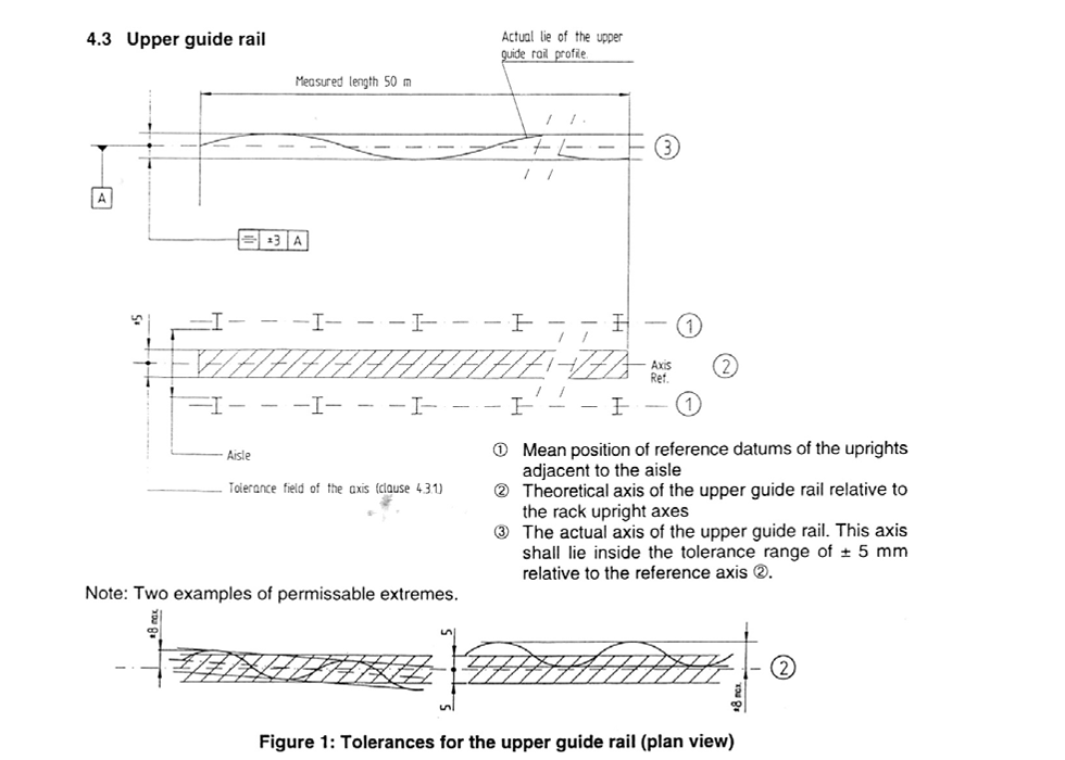
The tolerance of the longitudinal axis of the guide rail, in relation to the mean of the centrelines of the rack structure uprights along an aisle, shall not exceed ±5 mm over a measured length of 50 m.
H3: Horizontal Deviation and Rack Structure
When unloaded, the horizontal deviation of the upper guide rail from its longitudinal axis relative to the rack structure shall not exceed ±3 mm.
H3: Lateral Deformation Under Load Near Rack Structure
The maximum lateral deformation (sagging and twisting) in the area of the guide rollers, resulting from horizontal forces with the load handling device extended and with the maximum load, shall not exceed 6 mm. This deformation must be considered when calculating clearances between the S/R machine and the rack structure.
H1: Rack Structure—The Most Critical Component
H2: Rack Structure Classification According to FEM 9.831
The FEM 9.831 standard defines two primary rack structure tolerance categories:
Class 100 Rack Structure (Lower tolerance and deformation values) :
For control system B in conjunction with S/R machines without positioning aids at the storage position
Usually for storage systems of light weights and low to medium height (max. 18 metres)
Requires more precise manufacturing and erection of the rack structure
Class 200 Rack Structure (Higher tolerance and deformation values) :
For control systems A, C, and D in conjunction with S/R machines having positioning aids at the storage position or manually controlled
Accommodates heavier loads and greater heights
Allows for larger tolerances in the rack structure
The choice between Class 100 and Class 200 rack structure has profound implications for manufacturing tolerances, erection tolerances, and allowable deformations.
H2: Manufacturing and Erection Tolerances for Rack Structure
H3: Rack Structure Tolerances in the x-Direction
For both Class 100 and Class 200 rack structure, the following tolerances apply in the x-direction (aisle length):
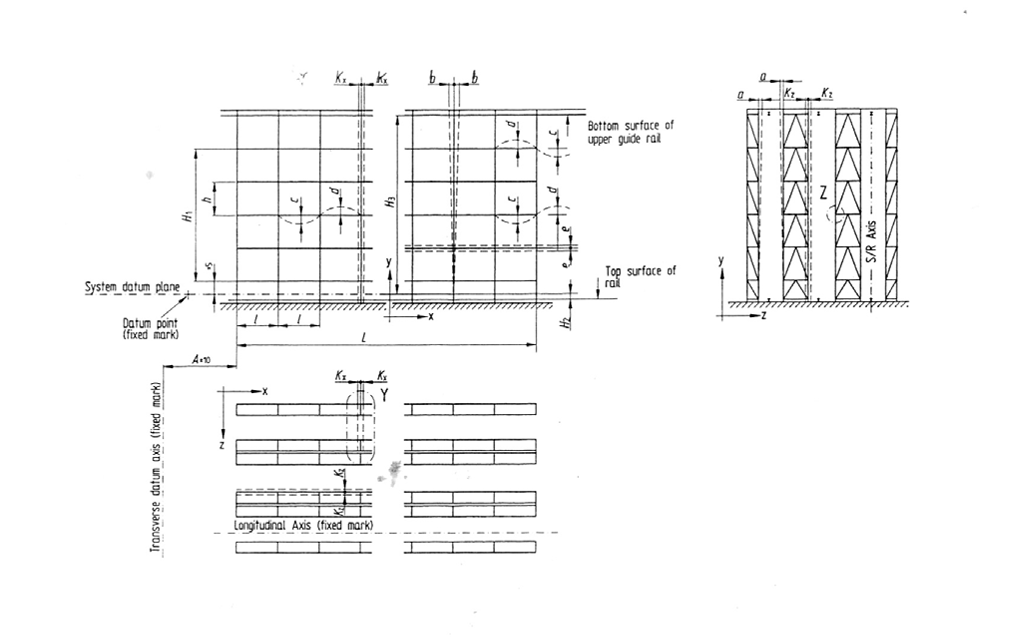
The tolerance field Kx of mutually opposite uprights in the rack structure, resulting from offset of the upright feet, slanting, precurvature of the supports and frames over the total height, must not exceed 15 mm
The pitch of individual rack structure aperture uprights (l) must lie within a tolerance of ±3 mm
The centreline of the first rack structure upright must lie within a tolerance of ±10 mm in relation to the horizontal transverse datum
Up to a length of 40 m, the overall length (L) of the rack structure shall not deviate from the nominal dimension by more than ±20 mm or, in the case of longer rack structure, by more than ±0.5%
Following erection, the individual axes of the uprights in the rack structure have to be fixed in accordance with the actual dimensions on site; however, the tolerances of the following dimensions must be maintained:
First row of rack structure uprights
Rack aperture dimensions
Overall length of the rack structure
H3: Rack Structure Tolerances in the z-Direction
For both Class 100 and Class 200 rack structure, the following tolerances apply in the z-direction (aisle lateral):
The outer extremity of the uprights and the beams on the aisle side of the rack structure must lie within a tolerance of Kz = ±15 mm in relation to the vertical, tolerance-free aisle datum plane (x-y)
Mechanical devices (e.g., back stops) at the rear of pallets to prevent them being pushed through the rack structure must be fixed within a tolerance of ±5 mm in relation to the edge of the upright
H3: Rack Structure Tolerances in the y-Direction
The level tolerance at each individual level of all support beams situated in individual aisles and all aisles served by the same rack structure must be within the following values:
The distance (h) between two adjacent beam levels in the rack structure shall not deviate from the nominal dimension by more than ±5 mm
The height (H₁) between the lowest and highest beam level in the rack structure, determined from the actual situation, may have a total tolerance of ±0.5% of the height H₁
The level tolerance of the lowest beam level in the rack structure in relation to the fixed level datum may be ±5 mm
If possible, within the area of a storage location in the rack structure, the top surface of the rear supporting beam should not be higher, but no more than 4 mm lower, than the top surface of the foremost beam. Positive tolerances of +2 mm are allowed
H2: Deformation of Rack Structure Due to External Forces
External forces such as snow loads, reaction forces of S/R machines, temperature influences, and particularly wind pressures result in various deformations of the rack structure.
H3: Wind Forces and Rack Structure
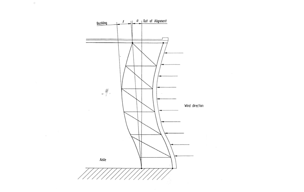
For silo structures, wind forces in the z-direction may lead to critical deformations of the outer rack structure. Equally, wind forces in the x-direction are capable of generating critical deflections on the gable end of the rack structure.
Unless otherwise agreed or stipulated in legal requirements, the functionality of the rack structure should be guaranteed in all areas of the warehouse up to wind velocities of 70% (dynamic pressure 50%) of the values stated in national rules relating to design loads for buildings. This reduced value corresponds to a wind velocity of approximately 80 to 100 km/hour.
In the conditions of lateral wind forces being imposed on the outer rack structure, deformations as shown in Figure 4 of the standard would occur. If deformation of the rack structure uprights exceeds 15 mm (i.e., buckling measured from a line drawn between the base centre point and the top of upright centre point to the extremity of the deflection), this can necessitate the increase of the clearance between the aisle width load faces.
H3: Deformation of Rack Structure from Working Load
Pallet loads placed within rack structure apertures cause the support beams to deflect and the rack structure uprights to compress. This deflection and compression results in a downward movement of the rack structure in the y-direction. This compression is cumulative over the total height of the rack structure.
The standard provides specific deformation limits for supporting beams in the rack structure under load:
| Beam Type in Rack Structure | Class 100 | Class 200 |
|---|---|---|
| Sagging (c) in rack structure | 300/l | 200/l |
| Hogging (d) in rack structure | 200/l | 200/l |
| Maximum deformation of rack structure beams | 10 mm | 15 mm |
For cantilever beams in the rack structure, the deflection at the end of the cantilever beams will be less than that of an adjacent three-position aperture but will be 20% larger than an adjacent two-position aperture in the same rack structure.
H3: Additional Deformations of Rack Structure from Column Inclination
The inclination of columns in the rack structure resulting from external forces and/or erection can lead to additional horizontal deformations. These “second order” deformations of the rack structure shall be taken into account in the design of the rack structure.
H2: Permissible Deformations of Rack Structure
The permissible deformations a e b (in the z- and x-directions respectively) are listed in the standard for different warehouse heights and control modes. For Euro pool pallets 800 × 1200 mm stored in the rack structure, the values are particularly critical at the upper levels.
For rack structure of concrete construction, the standard notes that these are generally of substantially stiffer construction in the longitudinal direction than steel rack structure. However, manufacturing and erection tolerances of concrete rack structure are likely to be substantially higher.
H1: Clearance Types and Their Relationship to Rack Structure
H2: Entry Clearances and Rack Structure
Entry clearances are the clearances between the load handling device and the load make-up accessory within the rack structure. The FEM 9.831 standard defines four entry clearance dimensions that must be maintained relative to the rack structure:
x₁: Clearance on the side of the load handling device which is furthest from the mast and nearest to the rack structure upright
x₂: Clearance on the side of the load handling device which is closest to the mast and nearest to the rack structure upright
y₁: Clearance between the load handling device and the load supporting beam of the rack structure
y₂: Clearance between the load handling device and the load make-up accessory within the rack structure
For twin mast S/R machines, x₂ is used for either side of the rack structure. In all cases, the largest cross-section of the load handling device entering the load make-up accessory must be taken into consideration relative to the rack structure components.
H2: Rack Compartment Clearances Within the Rack Structure
Rack compartment clearances are the minimum distances between the unit load and the rack structure components:
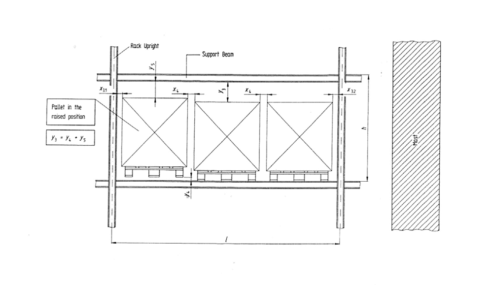
x₃: Between unit loads and the rack structure uprights on both the mast-side and furthest-from-mast sides
x₄: Between individual unit loads within the rack structure
y₃: Between the top of the unit load and the rack structure and/or other obstructions (e.g., sprinklers)
The rack compartment clearance y₃ consists of the lower dimension y₄ (top of lower support beam to the underside of the raised load handling device) plus clearance y₅ (top of raised load to underside of upper support beam in the rack structure).
H2: Aisle Clearances and Rack Structure
Aisle clearances are the minimum distances between the S/R machine and the rack structure:
z₁,₁: Between the unit load and any obstruction on the building side adjacent to the rack structure
z₁,₂: Between the unit load and rack structure inner racks
z₂,₁: Between the outermost point of the lifting carriage or the unit load and the rack structure with a protruding load in the stored position (outer rack side)
z₂,₂: Ditto, inner rack structure side
z₃,₁: Between fixed obstructions on the S/R machine and the stored load or the rack structure (outer rack side)
z₃,₂: Ditto, inner rack structure side
H1: The Control Calculation Methodology for Rack Structure
H2: Summary of Influencing Factors on Rack Structure Clearances
The FEM 9.831 standard provides a comprehensive table of influencing factors that affect clearances. These factors are categorized by their source, with the rack structure contributing multiple critical factors:
T30: Tolerance field of opposite uprights in the rack structure
T31: Supporting beam level tolerance in the rack structure
T32: Height difference between supporting beams in the rack structure
T33: Distance between supporting beams in the rack structure
T34: Tolerance of rear obstruction in the rack structure
V20: Verticality of the rack structure
V21: Upright compression in the rack structure
V22: Deflection of supporting beams in the rack structure
V23: Deformation of inner rack structure racks
V24: Displacement of the pallet pick-up point in the rack structure
Each factor contributes a tolerance (T) or deformation (V) value that must be summed in the worst-case calculation for the rack structure.
H2: The Worst-Case Condition for Rack Structure
The worst-case condition for the rack structure occurs with all tolerances and deformations at a maximum value and in the least favourable direction. The result is a dimension which must be related correctly to the required clearance between the S/R machine and the rack structure.
If the supply and erection of the individual components of the system—including the rack structure—are divided between separate suppliers, it is advisable to use the clearances derived from the worst-case condition.
The calculation example in the standard fundamentally assumes coincidence of the least favourable maximum values for the rack structure. This conservative approach ensures operational safety even under the most adverse conditions affecting the rack structure.
H1: Calculation Examples from the FEM 9.831 Standard for Rack Structure
H2: Example 1—Racking Class 200 Rack Structure, Control Modes A, C, D
Technical Data for the Rack Structure:
Silo/rack clad construction with pallet rack structure
Clear building height: 24 m for the rack structure
Rack structure length: 80 m
Single-mast S/R machine serving the rack structure
Maximum rated load: 1000 kg per rack structure position
Wheel base of S/R machine: 3.0 m
Euro pool pallet load make-up accessory in the rack structure
Maximum dimensions of unit load (x, z, y): 900 × 1300 × 1750 mm in the rack structure
Three unit loads per rack structure aperture
No long-term deformation of load make-up accessory and of load in the rack structure
Pallets presented to S/R machine by conveyor system with fixed stop adjacent to the rack structure
H2: Example 2—Racking Class 100 Rack Structure, Control Mode B
Technical Data for the Rack Structure:
Free-standing rack structure
Building height: 16 m for the rack structure
Rack structure length: 51 m
Single-mast S/R machine serving the rack structure
Maximum rated load: 1000 kg per rack structure position
Wheel base of S/R machine: 2.4 m
Euro pool pallet load make-up accessory in the rack structure
Maximum dimensions of unit load (x, y, z): 900 × 1300 × 1100 mm in the rack structure
Three-position pallet aperture in the rack structure
Pallets presented to S/R machine by conveyor with fixed stop adjacent to the rack structure
H2: Analysis of Calculated Clearances for Rack Structure
The calculation examples yield the following entry clearances for the rack structure:
| Clearance Relative to Rack Structure | Example 2 (Class 100, Mode B) | Example 1 (Class 200, Mode A) | Example 1 (Class 200, Mode C) | Example 1 (Class 200, Mode D) |
|---|---|---|---|---|
| x₁ (rack structure clearance) | 28 mm | 16 mm | 29 mm | 22 mm |
| x₂ (rack structure clearance) | 32 mm | 18 mm | 35 mm | 24 mm |
| y₁ (rack structure beam clearance) | 21 mm | 18 mm | 17 mm | 17 mm |
| y₂ (rack structure entry clearance) | 26 mm (6 mm) | 19 mm | 18 mm | 18 mm |
The rack aperture clearances within the rack structure are equally instructive:
| Clearance Within Rack Structure | Example 2 (Class 100, Mode B) | Example 1 (Class 200, Mode A) | Example 1 (Class 200, Mode C) | Example 1 (Class 200, Mode D) |
|---|---|---|---|---|
| x₃ (rack structure upright clearance) | 67 mm | 30 mm (7 mm) | 67 mm | 67 mm |
| y₃ (rack structure vertical clearance) | 76 mm | 92 mm | 101 mm | 101 mm |
These calculations demonstrate how control mode and rack structure class significantly influence required clearances. Mode A (manual control) generally requires larger clearances than automated modes, while Class 100 rack structure (with lower tolerance values) requires different clearance considerations than Class 200 rack structure.
H1: Practical Considerations for Rack Structure Design
H2: Compensating for Tolerances and Deformations in Rack Structure
In some cases, tolerances and deformations which combine in one direction may be compensated for by adjustments on the S/R machines relative to the rack structure. Examples include:
Alignment of the mast in the x-direction to the rack structure
Adjusting the y-axis marks at the upper levels of the rack structure after partly filling the racking to take account of compression of the rack structure uprights
Fino a 2/3 of the rack structure compression can be compensated for by placing the positioning marks in a lower position. Part of the beam deflection in the rack structure (approximately 30%) can be compensated for by lowering the position at which the forks are retracted.
H2: Special Considerations for Rack Structure with Euro Pool Pallets
In silo or clad rack structure which stores Euro pool pallets type I (800 × 1200 mm), the lateral clearances for fork entry in the fork apertures are to be considered as particularly critical.
If loaded pallets are heavy such that they necessitate the use of forks having large cross-section dimensions, it could be possible that the system may not function under conditions of maximum tolerances and deformations at the top pallet level of the rack structure—particularly high wind forces in the x-direction.
Under these circumstances, special measures may have to be taken for the rack structure such as:
Reducing the tolerance values given in the standard for the rack structure
Increasing the wind bracing of the rack structure
Restricting operations when severe wind conditions in the x-direction prevail against the rack structure
H2: The Role of Positioning Aids in Rack Structure Operation
The choice of control mode determines whether positioning aids are required for the rack structure:
Control Mode B (automatic with coordinate positioning) does not require positioning aids at the storage position in the rack structure
Control Modes A, C, and D require positioning aids at the storage position for Class 200 rack structure
For automated systems, a calculation should be made by the person responsible for the design of the rack structure. From this, a decision can be made to determine the classification and control mode for the rack structure.
H1: Conclusion
The systematic calculation of tolerances, deformations, and clearances is the cornerstone of safe and efficient high-bay warehouse rack structure design. The FEM 9.831 standard provides the essential framework for this discipline, offering quantified values for every component—from the floor slab and guide rails to the unit load and rack structure—and a methodology for combining these values into meaningful clearance calculations.
We have seen that the worst-case condition—where all tolerances and deformations are at their maximum values and in the least favourable direction—forms the basis for determining required clearances between the S/R machine and the rack structure. This conservative approach ensures operational safety but must be balanced against the economic imperative to maximize storage density within the rack structure.
The choice of control mode (A through D) and rack structure class (100 or 200) has profound implications for allowable tolerances and required clearances. Class 100 rack structure with lower tolerance values is suitable for lighter loads and lower heights, while Class 200 rack structure with higher tolerance values accommodates heavier loads and greater heights but requires more sophisticated control systems.
For Euro pool pallets—the most common load make-up accessory in European high-bay warehouses—the entry clearances relative to the rack structure uprights are particularly critical, especially at upper levels where wind-induced deformations of the rack structure are greatest.
Ultimately, the FEM 9.831 standard serves a vital purpose: defining the interfaces between the components of a high-bay rack structure sistema. By establishing clear responsibilities and quantifiable limits for each component of the rack structure, the standard enables system integrators, equipment manufacturers, and warehouse operators to design rack structure systems that are both safe and economically optimal.
The calculation examples demonstrate that typical clearances range from 16 to 35 mm for entry clearances and from 30 to 101 mm for rack compartment clearances, depending on the specific combination of rack structure class and control mode. These figures provide practical benchmarks for rack structure system designers.
As high-bay warehouses continue to grow taller and S/R machines continue to operate faster, the importance of precise rack structure clearance calculation will only increase. The FEM 9.831 standard—now in its updated 2012 edition as FEM 9.831-1—remains the definitive reference for this critical engineering discipline. For rack structure designers, system integrators, and warehouse operators alike, mastering these calculation principles is essential for building warehouses that are safe, efficient, and economically viable.
H2: Frequently Asked Questions
What is the difference between Class 100 and Class 200 rack structure according to FEM 9.831?
Class 100 rack structure features lower tolerance and deformation values and is typically used for control system B with S/R machines without positioning aids at the storage position. It is suitable for light weights and low to medium height (max. 18 metres). Class 200 rack structure features higher tolerance and deformation values and is used for control systems A, C, and D with S/R machines having positioning aids at the storage position or manually controlled systems.
How do wind forces affect rack structure clearance calculations?
Wind forces in the z-direction can cause critical deformations of outer rack structure in silo structures, while wind forces in the x-direction can generate critical deflections on gable ends of the rack structure. The standard requires that rack structure functionality be guaranteed up to 70% of design wind loads (approximately 80-100 km/hour). For Euro pool pallets, wind-induced deflections of ±10 mm at upper levels of the rack structure may necessitate special measures such as fine positioning or rack structure strengthening.
Can tolerances and deformations of the rack structure be compensated for after installation?
Yes. In some cases, tolerances and deformations that combine in one direction may be compensated for by adjustments on the S/R machines relative to the rack structure—for example, alignment of the mast in the x-direction to the rack structure or adjusting y-axis marks at upper levels after partial rack filling to account for rack structure upright compression. Up to 2/3 of rack structure compression and approximately 30% of beam deflection in the rack structure can be compensated for through positioning mark adjustments.
Why are Euro pool pallets considered particularly critical in rack structure clearance calculations?
Euro pool pallets (800 × 1200 mm) have relatively narrow fork entry apertures, and the actual dimensions must be checked particularly in the area of these apertures due to the possibility of reduced clearances between the forks and the rack structure. Wooden pallets are also subject to shrinkage from drying out and may undergo elastic and/or plastic deformation over longer storage periods within the rack structure. When heavy loads (over 800 kg) require wider telescopic forks, the entry clearances relative to the rack structure uprights become especially critical.
What is the worst-case condition in FEM 9.831 rack structure clearance calculations?
The worst-case condition occurs when all tolerances and deformations of the rack structure are at their maximum values and in the least favourable direction. The calculation fundamentally assumes coincidence of the least favourable maximum values for the rack structure. This conservative approach ensures operational safety even under the most adverse conditions affecting the rack structure and is recommended when system components are supplied by different vendors.
Geelyracks specializes in the production of warehouse racks and is a global rack customization expert: https://geelyracks.com/
Se avete bisogno di disegni CAD e preventivi perfetti per le scaffalature da magazzino, contattateci. Possiamo fornirvi servizi e preventivi gratuiti di pianificazione e progettazione di scaffalature per magazzini. Il nostro indirizzo e-mail è: jili@geelyracks.com