📐 "Ensimmäiset 50 yrityskyselyä saavat mukautetun 3D-varaston suunnittelun" Suunnitelma















Steel Storage Rack Structural Design: The Engineering Guide to the Assembled Rack, Integrated Systems, and Rack-Clad Buildings
Executive Summary
This guide unpacks the structural engineering substance behind a dedicated steel storage rack design specification and organises it around the system most warehouses actually buy: the assembled rack. . assembled rack — the adjustable, bolt-and-clip pallet racking that fills distribution centres worldwide — is examined in depth, from its mechanical locking connections and cold-formed uprights to its semi-rigid beam joints and bracing logic.
The article then places the assembled rack beside its heavier cousins, the integrated high-bay rack and the rack-clad building, so the differences in analysis are never blurred. Material selection, the limit state design philosophy, the full load and combination discipline (dead, live, vertical impact, horizontal, wind, seismic), and the testing regime that closes theory’s gaps are all covered. For the assembled rack specifically, the guide adds bay geometry, connector types, procurement checklists, a buyer-facing comparison, and the field lessons that separate a safe assembled rack installation from a costly one.
The objective is simple: give the reader enough structural fluency to specify, buy, inspect, or sell the assembled rack with confidence, and to do so in language a search engine can rank and a procurement manager can act on.
What the Steel Racking Structural Design Specification Actually Covers
A storage rack is one of the few structural systems where the contents are the load, where the structure is struck repeatedly by motorised traffic, and where the geometry is tuned millimetre by millimetre to the box that rests on it. The specification examined here was written to give that peculiar system a disciplined design basis, and it was built on a foundation of physical testing rather than textbook elasticity alone.
The document was developed under the authority of the China Association for Engineering Construction Standardization, with technical sponsorship from the National Technical Committee for Thin-Walled Steel Structures. That lineage matters for credibility: this is a consensus standard compiled by practising engineers and reviewed by a national committee, not a vendor white-paper. The names attached to its drafting — design institutes and universities that spent years correlating laboratory collapse tests with real warehouse behaviour — are the kind of provenance a procurement team should look for before trusting any design rule.
The Three Structural Families the Code Distinguishes
Before a single formula is touched, the code forces a classification decision, and in field practice this is exactly where weak designs begin. Three families are recognised, and they are not interchangeable:
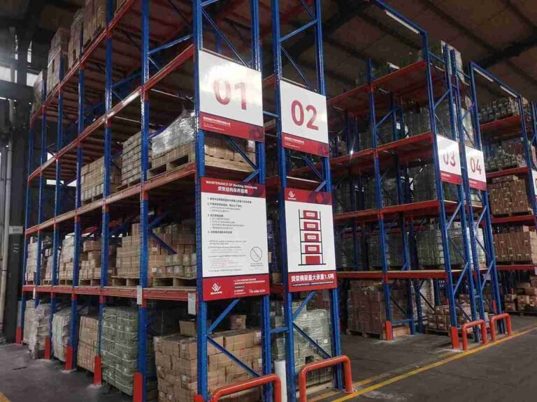
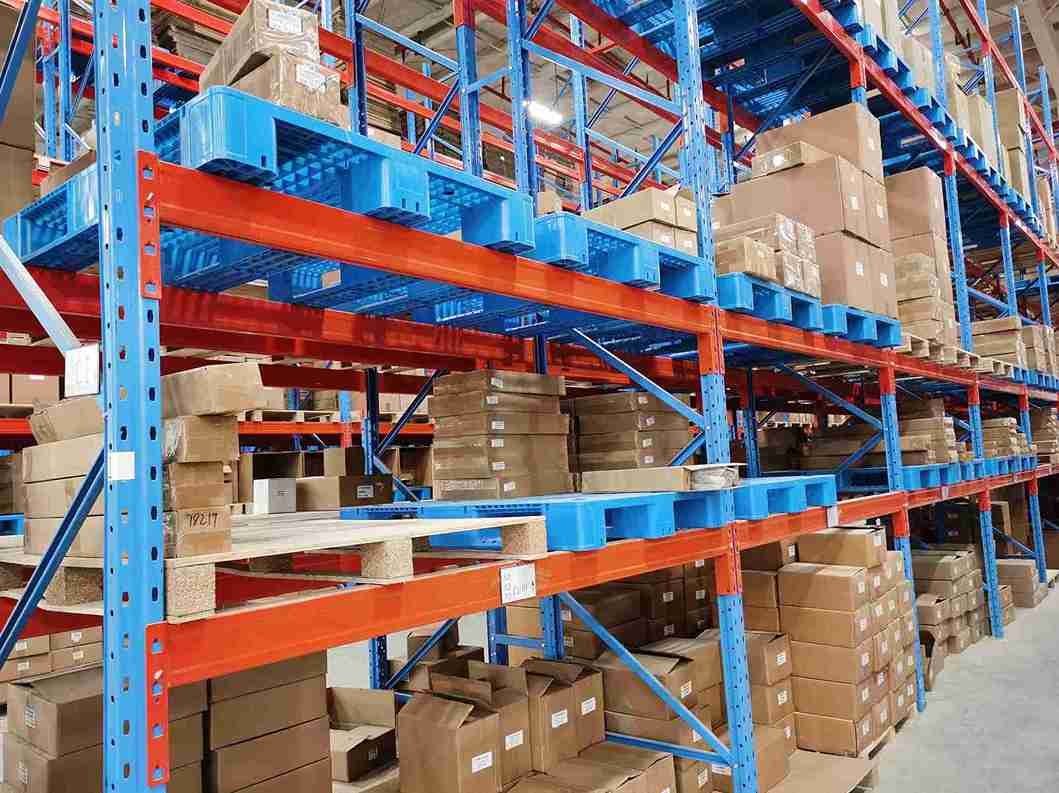
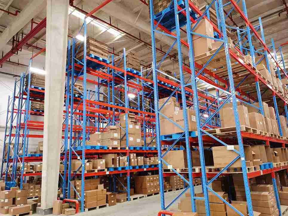
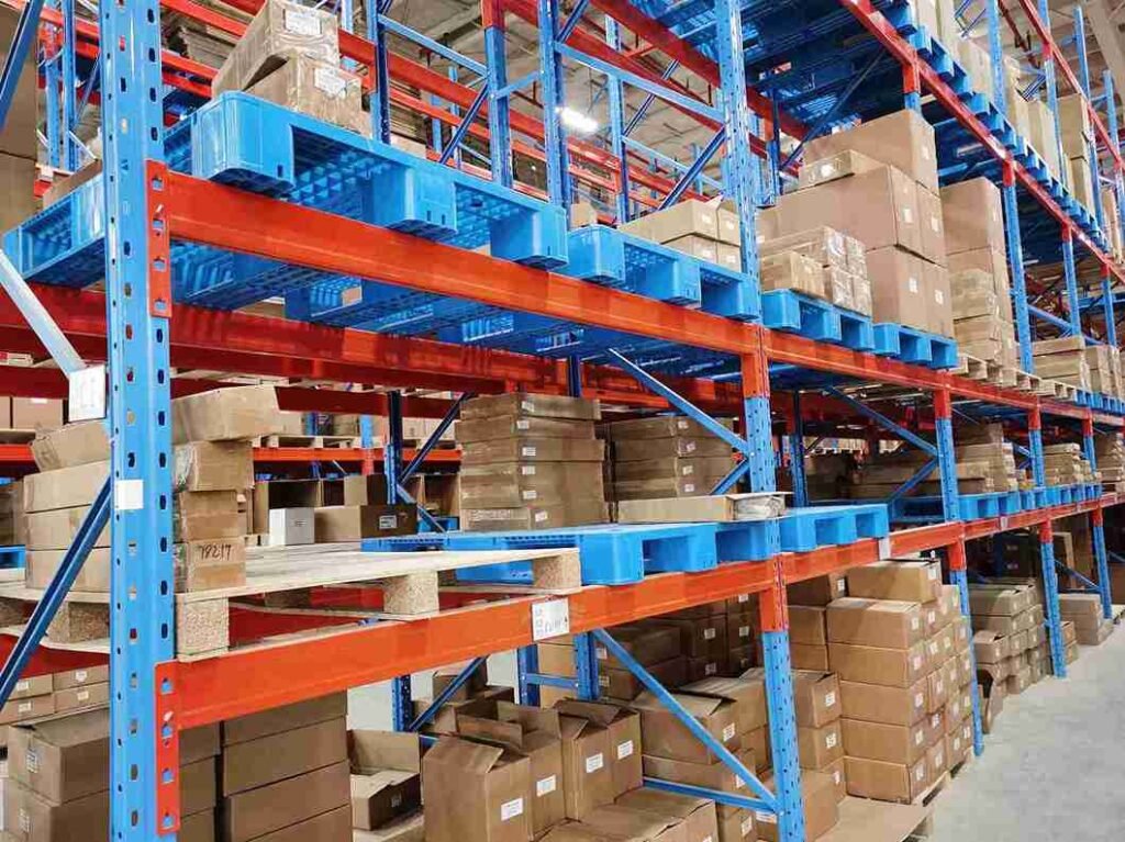
- Assembled rack (组装式货架) — the adjustable pallet rack most people picture. Beams and columns are joined by mechanical locking devices, the system is detached from the building, and it can be disassembled and reconfigured. The assembled rack is the dominant species in distribution centres and the primary subject of this guide.
- Integrated (monolithic) rack (整体式货架) — the structural members are welded or bolted into a fixed system, still detached from the building envelope, but not intended to be taken apart. These appear in automated and semi-automated high-bay warehouses.
- Rack-clad or shelf-supported building (库架合一式货架) — the rack is the building. Beyond carrying goods, the structure bears the roof and wall cladding and becomes the skeleton of the warehouse.
If an assembled rack connection model is applied to a rack-clad structure, or a monolithic lattice column is treated like a bolt-together upright, the numbers may look confident while being quietly unsafe. The specification splits its Chapters 5, 6, and 7 along these lines for a reason, and the assembled rack chapter is where most of the world’s steel racking lives.
Why This Code Exists and Who It Protects
The preamble is candid about intent. Modern industry needed high-density, automated storage to cut handling cost and floor area, and the multi-tier steel rack became the default system for that ambition. The code was written so a designer has a consistent rulebook instead of improvising. Its stated directive — technically advanced, economically reasonable, safe, applicable, and quality-assured — is the lens through which every later clause should be read. A specification that over-builds to the point of absurd cost is no better than one that strips away a proven safety margin; the assembled rack sits in the middle, where efficiency and safety must coexist.
The specification also sits inside a wider family of codes. It defers to the Unified Standard for Building Structural Design, the Load Code for Building Structures, the Technical Code for Cold-Formed Thin-Walled Steel Structures, and the Code for Design of Steel Structures. Outside China the conceptual neighbours are the RMI / ANSI MH16.1 specification in North America and EN 15512 (built on the former FEM 10.2.02) in Europe. The assembled rack is treated by all three traditions, which makes it the most portable and comparable of the three families.
Material Selection: The Foundation Nobody Should Rush
A rack is only as trustworthy as the steel approved on the material certificate. The specification is opinionated here, and responsible manufacturers agree with its opinion.
Carbon and Low-Alloy Steels for Rack Load-Bearing Members
For load-bearing members, the code steers designers toward Q235 carbon structural steel ja Q345 low-alloy high-strength steel as workhorse choices, with explicit allowance to use other grades where reliable justification exists. In everyday rack manufacturing these map to the mild-steel and 50-grade families familiar to any fabricator. The principle is identical: pick the steel to the importance of the member, the load character, the connection method, and the service environment.
Experienced engineers reject “cheaper” import coils that meet the yield point on paper but fail on the sulfur and phosphorus limits the code demands. Those chemistry limits govern weldability and brittle-fracture resistance. The specification requires load-bearing steel to carry certified tensile strength, elongation, yield strength, and S/P content, with carbon content certified for welded structures and a cold-bend test certificate for cold-formed sections. One rule worth repeating: at service temperatures at or below a defined cold threshold, rimmed (boiling) steel of the lower grade is not permitted for load-bearing rack members. Cold-temperature brittleness is exactly the failure mode no freezer warehouse wants at minus twenty.
Connection Materials and Why They Fail First
In failure investigations, the connection almost always fails before the member. The specification therefore dedicates real estate to connection consumables: manual welding electrodes matched to base-metal strength; automatic and semi-automatic welding wire and flux compatible with the parent metal; gas-shielded welding wire as a high-deoxidation alloy; ordinary bolts for secondary connections; high-strength bolts for primary ones; and anchor bolts cast into the foundation. The assembled rack depends on this last category least — its uprights are typically located, not anchored — but the principle holds: a rack analysed perfectly but joined with the wrong electrode, or an anchor specified at the wrong grade, fails at the joint long before the maths predicts a member failure.
Cold-Forming Strength Enhancement the Designer Can Claim
Cold-formed thin-walled members gain strength from the cold-bending process itself — the corners work-harden. The specification lets designers use a cold-forming-enhanced strength design value for fully effective sections, calculated from a formula that folds in a forming-method coefficient, the tensile-to-yield ratio, the number of corners, the corner angle, and the section centreline length. For high-frequency welded rectangular and square tubes the coefficient is set one way; for round tubes and open sections another. Designers who ignore this over-size sections by 8–12 percent, which is pure wasted steel. Others “claim” cold-forming gain on a section not actually cold-formed to the assumed process, producing an assembled rack that is light on paper and light in reality, in the wrong way.
Weld Procedure Qualification and Bolt Preload Discipline
The specification treats welding as a controlled process, not a casual skill. Every production weld on a load-bearing member should be backed by a qualified weld procedure specification (WPS) and performed by welders whose qualification is current for the process and position. For the high-volume seams on uprights and beams, procedure qualification coupons that are sectioned and tested beat a piece of paper. The code’s strength tables for butt welds and fillet welds assume a competent, qualified weld; an unqualified weld quietly lowers real capacity below the table value.
For the friction-type high-strength bolts the code favours in fixed structures, the governing quantity is the slip resistance at the faying surface. The design shear capacity is the product of a coefficient (which differs for hot-rolled versus cold-formed members), the number of friction surfaces, the slip coefficient (set by surface treatment), and the specified pretension. Shipments where connector plates arrive with mill scale intact yet are specified for a high slip coefficient will slip at a fraction of the design load. The code even directs that the cleaning direction be oriented perpendicular to the force — a detail that sounds fussy and matters enormously when the joint sees repeated cyclic load from a passing stacker.
Coating Systems That Survive the Warehouse Environment
Although the structural code is primarily about strength, the durability of that strength depends on the corrosion protection system, and coating selection should be treated as a structural decision because rust is a section-thinning process that attacks exactly the thin plates most sensitive to local buckling.
For indoor dry storage, a standard powder coat or electro-static spray over a cleaned substrate is usually sufficient. For cold stores, outdoor racks, or food and chemical environments, hot-dip galvanizing is specified, often with a hygienic topcoat. The trap to avoid is galvanizing a tightly tolerance-interfering connector: the coating thickness changes the fit of a beam-end clip, and a clip that will not seat is a clip that will not carry. The assembled rack lives or dies on that clip seating correctly every time.
The Limit State Philosophy Every Rack Engineer Must Internalize
The code adopts a probability-based limit state design method expressed through partial safety factors. For anyone raised on allowable-stress design, this is the single biggest mental shift.
Ultimate Limit State vs Serviceability Limit State
Two limit states govern everything. The ultimate limit state means the structure must not collapse, overturn, or suffer a strength failure; here design loads and strength design values are used. The serviceability limit state means the rack must remain usable — deflections, vibrations, and local distortions stay within tolerable bounds; here characteristic loads and allowable deformations are used, and every partial factor is taken as 1.0.
A beam can pass the strength check and still be unusable because it deflects like a diving board, dumping pallets off the back of a forklift. The code insists both states be checked. The pallet beam deflection limit is set at a fraction of the span (commonly around span/200), and the vertical impact load is deliberately excluded from the deflection check because impact is a transient event, not a service condition. This discipline applies to the assembled rack every bit as much as to its fixed cousins.
There is a second serviceability concern the specification handles with intelligence: the reduction coefficients applied to strength design values when the connection or fabrication condition is less than ideal. A single-angle member connected on one side — a common lazy detail — gets a harsher reduction for compression stability because the eccentric weld path invites flexural buckling. When several adverse conditions stack on the same member, the factors multiply. A “minor” 5 percent reduction can cascade into a 25 percent capacity loss across three coincident penalties. The lesson for detailers is blunt: design the connection as carefully as the member.
Safety Grades and What “Grade Three” Really Means
The specification assigns a typical safety grade of three to ordinary rack structures, with the door open for special structures to be re-graded by engineering judgement. In plain terms, the reliability target baked into the partial factors already assumes a normal warehouse, not a vault. If a rack holds hazardous material, sits in a seismic zone, or supports a building, it is firmly in “re-grade and document why” territory. Where no clean calculation method exists for an unusual assembled rack form, the code tells the designer to fall back on model or full-scale testing to determine the governing parameters and capacity. That is the honest admission that a bolt-together rack with semi-rigid joints is a semi-empirical structure.
Loads and Load Combinations: The Heart of Rack Design
The load combination that is forgotten is the one that governs. The specification is unusually clear about the load taxonomy, and the assembled rack must be checked against every part of it.
Dead Load, Live Load, and the Vertical Impact Load Engineers Cannot Ignore
The code recognises these load categories on a rack:
- Dead load — the self-weight of the rack; for rack-clad structures it also includes roof and wall self-weight.
- Rack live load — the weight of goods, boxes, or pallets placed on the structure. This is the load the rack is sold to carry.
- Vertical impact load — the dynamic slam when a storage machine deposits a load, treated as a fraction of the static design value of a single pallet-plus-goods unit at the worst position.
- Horizontal load — from initial member curvature, erection tolerance, load eccentricity, and light contact with handling equipment.
- Wind, snow/roof live load, and seismic action — relevant for outdoor, rack-clad, or high-bay structures.
The vertical impact load deserves respect. When a cleat, beam, or end connection that directly carries live load is designed, the impact at the most unfavourable location must be included, and the resulting stress must still sit under the strength design value. Miss this and a beam-end weld that survives static loading cracks after a few thousand pallet placements. Field reports show exactly that failure mode in an under-specified beam-to-upright connection on an assembled rack.
Horizontal Loads From Imperfections and Forklift Contact
This is the clause general-buildings engineers find surprising. A rack attracts horizontal force from its own imperfections — columns are never perfectly straight, erectors never perfectly plumb, pallets never perfectly centred. The code quantifies it pragmatically:
- For a sway (laterally unrestrained) assembled rack, the horizontal load at each beam-to-column node can be taken as about 1.5 percent of the sum of all dead and maximum live load transmitted through that node.
- For a non-sway (braced) assembled rack, the figure drops to about 0.5 percent.
For fixed racks served by stacker cranes, the code sensibly says: get the horizontal loads from the crane manufacturer’s data. Do not guess. A stacker crane is a precise, heavy, moving machine, and its dynamic envelope is a manufacturer’s promise, not an assumption to invent.
Seismic Action and the Base Shear Method
The code takes a measured view of earthquakes: for rack structures it considers horizontal seismic action only and ignores vertical seismic action. The horizontal base shear is computed with the familiar equivalent lateral force (base shear) method — total horizontal seismic action equals a seismic influence coefficient (a function of the structure’s fundamental period, site class, and near/far fault) multiplied by the equivalent total weight. The fundamental period can be found by a multi-degree-of-freedom analysis or a simplified empirical formula tied to rack height. The code also defines combination coefficients for live loads in the seismic check, which prevents crediting the rack with impossible simultaneous loading.
Putting It Together: The Six Combinations
For the ultimate limit state, the code gives a menu of combinations and tells the designer to take the most unfavourable:
- Dead + rack live load
- Dead + rack live + vertical impact
- Dead + rack live + horizontal load
- Dead + rack live + wind
- Dead + rack live + wind + horizontal load
- Dead + rack live + horizontal seismic action
For serviceability, combinations one through five are run with every partial factor set to 1.0. Indoor assembled rack and integrated systems are excused from wind and seismic combinations; outdoor and rack-clad structures must consider wind and the horizontal load acting together. A dedicated overturning check compares destabilising horizontal seismic or wind-plus-horizontal load against stabilising minimum gravity load. The overturning check is non-negotiable on any assembled rack taller than a person, because a tipping rack takes the whole aisle with it.
A Worked View of Why the Combination Sequence Matters
To make the combination logic concrete, picture a typical double-deep bay: dead load from steel, a rack live load per pallet position, a vertical impact allowance on the loaded beam, a horizontal sway load near 1.5 percent of the node load, and — for an outdoor version — a wind and snow case. Run them independently and each looks benign. Superpose them per the code’s six combinations and the seismic or wind-plus-horizontal case quietly governs the column and the base, while the dead-plus-live-plus-impact case governs the beam end.
The engineer who only checks dead-plus-live will size the beam correctly and the column wrongly. The error hides until the structure is erected and a gust or a quake arrives. On an assembled rack, that oversight is the difference between a routine installation and a collapse inquiry.
The Assembled Rack in Depth
The assembled rack deserves its own extended treatment because it is the system most readers will specify, buy, or sell, and because its behaviour is the least intuitive of the three families. The assembled rack is defined by demountability: beams clip into uprights through mechanical locking devices, the system stands free of the building, and the layout can be reconfigured as the operation changes. That flexibility is the assembled rack‘s great commercial strength, and it is also the source of its structural subtlety.
What Makes an Assembled Rack Structurally Distinct
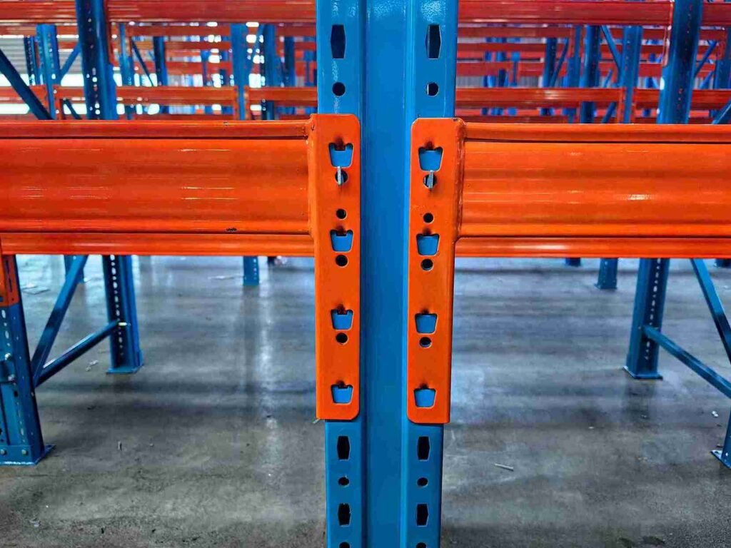
The defining feature of the assembled rack is the semi-rigid, mechanical beam-to-column connection. Unlike a welded frame, where joints are close to fixed, or a pin-connected truss, where they are close to hinged, the assembled rack connector sits stubbornly in between. The upright is a perforated, cold-formed member — often a lipped channel, or a rectangular/square/round tube — welded to a base plate and braced without gusset plates. The beam end carries a welded connector whose behaviour must be proven by test, not assumed. The assembled rack therefore cannot be analysed by the textbook elastic-frame methods alone; it is a semi-empirical structure whose real strength is demonstrated as much in the laboratory as on the drawing board.
Another distinction: the assembled rack is expected to be relocated. That expectation means its connections are designed for repeated assembly and disassembly, and its uprights are located on base plates rather than rigidly anchored in most indoor applications. A responsible assembled rack supplier will state plainly which connections are field-adjustable and which are not, because a connector forced beyond its design travel is a connector that will not carry.
Effective Section Method for the Assembled Rack
The assembled rack is overwhelmingly built from cold-formed thin-walled steel, and the analysis hinges on the effective section concept. For cold-formed members, tension strength is calculated on the net section (holes deducted); compression strength and stability on the effective section, where locally buckled portions of thin plates are removed; deformation and stability coefficients may be computed on the gross section. The assembled rack upright is uniquely hole-riddled — every upright is a perforated steel lattice.
The specification handles perforated compression plates with a sensible rule: if the hole falls in the ineffective (buckled) zone, ignore it; if it falls in the effective zone, deduct the hole width from the effective width. Round holes get a dedicated calculation method in the appendix. Modellers who have run both approaches in finite element software confirm the code’s simpler rule is conservative without being wasteful — exactly what a design rule should be for the assembled rack.
Pallet Beam Design With Semi-Rigid Connections
The pallet beam is the member everyone sees and the one most often under-designed on an assembled rack. The code says treat it as a simply supported beam by default, but the moment a mechanical beam-to-column connection is used, the partial fixity of that joint must be accounted for. The mid-span moment for a semi-rigidly connected beam is the simply supported moment scaled by a moment fixity coefficient, and that coefficient is itself a function of the beam’s span, its flexural stiffness, and the joint’s elastic constant — which must be determined by test.
The deflection uses its own deflection fixity coefficient. The beam’s maximum deflection is capped at a fraction of its span (around span/200), vertical impact is excluded from the deflection check, and each beam end typically carries a welded connector whose capacity is proven by test while its weld to the beam is checked for the beam’s moment and shear.
One number every assembled rack specifier should memorise: each end connection of a mechanically joined beam must resist an uplift force of around 1 kN without failure or loosening. That uplift is real — eccentric pallet placement and seismic sway try to peel beams off columns constantly. An assembled rack that cannot hold its beams down is an assembled rack waiting for its first dropped pallet.
Vertical Frame Columns and Effective Length on the Assembled Rack
The upright of an assembled rack is a perforated member joined by bracing, and its design is where the effective-length concept earns its keep, because a tall slender upright’s buckling capacity is governed by how it is restrained, not just by its material. The code splits the effective length by the bending axis. Bending about the axis perpendicular to the aisle (out-of-plane sway): for a sway frame, the effective length comes from a formula involving the column-base rotation stiffness and the equivalent ground-beam stiffness, read off a published chart; for a non-sway frame, it is simply the distance between out-of-plane restraints.
Bending about the axis parallel to the aisle (in-plane) depends on whether the bracing intersects the column. The overall in-plane stability of the vertical frame is checked as a lattice (built-up) member, with a virtual-axis effective length equal to the frame height times a coefficient that depends on where the load resultant sits relative to mid-height.
Engineers who skip the lattice check and analyse each assembled rack column as a lone strut then wonder why a whole frame buckled as a unit. The frame acts as a team; analyse the team. Construction tolerances matter here too. The code limits the maximum vertical deviation of an assembled rack to about 1/1000 of its full height — a tighter plumb tolerance than most assume, and one enforced on site because an out-of-plumb rack compounds the horizontal-load problem from day one.
Assembled Rack Bay Geometry and the Pallet Fit
The assembled rack is dimensioned around the load it carries, and the specification ties bay geometry to the goods. The aisle width is set by the normal running and operating requirements of the forklift, stacker, or other handling machine. The assembled rack is typically built from several vertical frames connected by beams at several levels; the frame width and beam length follow the pallet (load) dimensions, with the vertical frame width generally in one band and the beam length in another.
When fixing the load-cell (storage compartment) size, the clearance between boxes and between boxes and uprights is taken at a defined value. An assembled rack designed without respecting these clearances will either waste floor space or jam the forklift — and a jammed forklift is the precursor to an impact-damaged upright.
The economics of the assembled rack flow directly from this geometry. Because the assembled rack is adjustable, a warehouse can change its pallet profile without replacing the steel, which is why the assembled rack dominates general distribution. But that adjustability demands disciplined load posting, because a reassigned bay may quietly exceed its original design load.
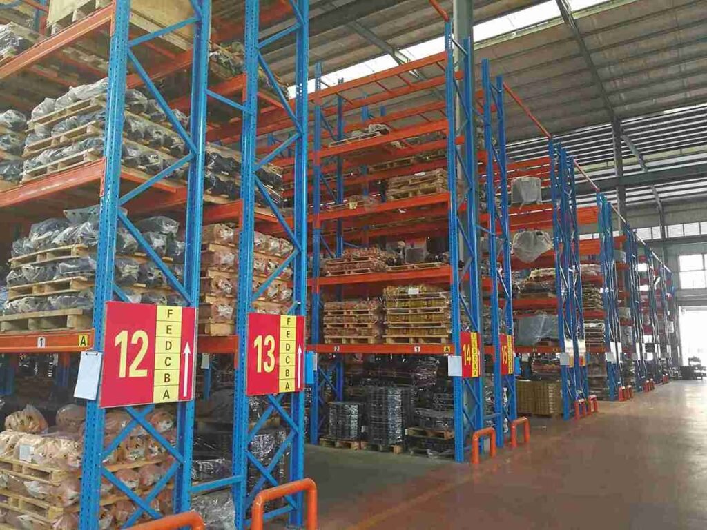
Assembled Rack Bracing and Global Stability
A non-sway assembled rack must carry vertical bracing in the plane of the vertical frames along the aisle direction, plus horizontal cross-bracing or fixed horizontal shelves at the top and at the bracing intersections. Without that bracing, the assembled rack is a stack of loosely linked frames that will sway and eventually walk. The assembled rack depends on its bracing for the very stiffness that keeps the horizontal-load percentage small; remove the bracing and the sway frame factor jumps, the effective length grows, and the capacity collapses. Specifiers who treat bracing as optional trim on an assembled rack are, in effect, removing the structure’s skeleton.
Assembled Rack Connectors, Clips, and Beam-End Types
The connector is the heart of the assembled rack. The most common forms are the clip-in beam end (a stamped or cast lug that drops into the upright’s perforations and locks under load) and the bolted or pinned variant used where higher capacity is needed. The specification treats the connector’s capacity as a test-derived property, and for good reason: the real moment-rotation behaviour of a clip-in connection cannot be predicted from first principles with useful accuracy.
A quality assembled rack manufacturer publishes the test-derived load tables for each connector and each upright gauge, and a buyer should treat any assembled rack quote that omits those tables as incomplete. The beam-end weld that attaches the connector to the beam is checked for the beam’s moment and shear, and on a well-made assembled rack that weld, not the clip, is usually the conservative link.
Signage, Structural Diagrams, and Anti-Collision Details
The code’s construction chapter contains requirements that save lives and that every jurisdiction should mandate. Every assembled rack needs a permanent load-capacity sign stating the maximum unit load, the maximum uniform load per level, and/or the maximum total load per bay. Owners are forbidden from altering the system in ways that invalidate that sign. Every assembled rack ships with a structural diagram listing load magnitudes, positions, all possible structural forms, and deviation limits — one copy to the owner, one to the maker, one to the designer.
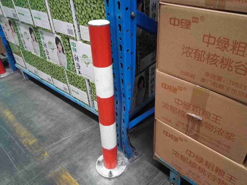
At column bases exposed to forklift impact, the code demands anti-collision protection (buffers or guard rails), double exterior columns where practical, and proof — by test where analysis is hard — that the assembled rack still stands if one exterior column loses all capacity. The guard must resist a defined static horizontal force over a set height without permanent deformation. Collapse investigations repeatedly trace a “freak” failure to a forklift kissing a bare column base with no guard — exactly the scenario the assembled rack rules are written to prevent.
Assembled Rack Procurement: How to Specify Without Guessing
For the buyer, specifying an assembled rack is less about steel grade and more about load definition. A precise assembled rack enquiry states the pallet dimensions and weight (including the goods), the load configuration per beam level, the required beam levels and bay count, the forklift type and aisle width, the floor flatness and capacity, and any seismic or wind exposure.
A vague assembled rack enquiry that merely states a need for “racking for the warehouse” produces a vague quote and, too often, a mismatched system. The specification’s load taxonomy maps directly onto a procurement checklist: declare the live load honestly, declare the impact environment honestly, and declare the seismic zone honestly. An assembled rack priced on understated loads is the most expensive rack a company can buy, because it fails or must be replaced.
Buyers evaluating an assembled rack supplier should ask for three things: the load-capacity certification backed by test data, the connector load tables, and references from installations of similar height and load. A supplier who cannot produce tested data for the exact assembled rack profile on offer is asking the buyer to accept analysis in place of evidence. The testing chapter of the specification exists precisely so that evidence is available, and a serious assembled rack maker will have it on file.
Assembled Rack vs Integrated vs Rack-Clad: A Buyer-Facing Comparison
| Attribuutti | Assembled rack | Integrated high-bay rack | Rack-clad building |
|---|---|---|---|
| Connection type | Mechanical clip / bolt, demountable | Welded or bolted, fixed | Welded/bolted, fixed, load-bearing envelope |
| Typical height | Low to medium (often < 12 m) | Medium to high (up to ~24 m) | High (roughly 8–25 m economical) |
| Reconfigurable? | Yes, core advantage | Ei | Ei |
| Automation fit | Manual / low-level VNA possible | Stacker-served automated | Automated, doubles as building |
| Seismic/wind in design | Indoor exempt; outdoor must include | Must include where applicable | Always included |
| Foundation | Base plates, usually located not anchored | Anchored, rigid raft/piles | Anchored, strict settlement control |
| Best when | Flexible, changing SKU profiles | Dense automated throughput | Land-limited, want building+rack as one |
The table is a starting point, not a verdict. The right choice depends on throughput, land cost, automation strategy, and seismic context. What the comparison makes clear is that the assembled rack wins on flexibility and speed of deployment, while the integrated and rack-clad systems win on density and automation. An assembled rack is rarely the wrong answer for a general warehouse; it is frequently the right one.
Common Assembled Rack Failures and the Field Lessons
Decades of inspection reports point to a short list of recurring assembled rack failures, and each maps to a clause in the specification. The first is the unguarded column base struck by a forklift — prevented by the anti-collision rules. The second is the overloaded bay, where a reassigned load exceeds the posted limit — prevented by disciplined load posting and owner training. The third is the missing or cut bracing, where an assembled rack installed “to save time” loses its global stability — prevented by treating bracing as structural, not trim.
The fourth is the mismatched connector, where beams from one system are forced onto another — prevented by supplier-certified compatibility. The fifth is the out-of-plumb frame, where an assembled rack erected without a survey leans into its neighbour — prevented by the 1/1000 tolerance and a commissioning check. Every one of these is avoidable, and every one is exactly what the specification’s assembled rack chapter was written to stop.
Integrated High-Bay Rack Design
When the rack becomes fixed, taller, and served by stacker cranes, the code shifts into its integrated-structure chapter. These are the backbones of automated warehouses.
Lattice Columns and Limb Geometry
An integrated rack is built from lattice (built-up) columns. In the cross-aisle direction, edge columns are typically double-limb lattices and middle columns are triple-limb (or two rows of double-limb). The analysis is a proper multi-bay portal analysis under the worst load combination when the top is tied by beams and bracing; where the top is free, the column is designed as a fixed-base cantilever.
Because goods are placed on only one side of a limb, the code requires the load eccentricity on the individual limb to be accounted for — single-sided loading is a bending problem, not a pure axial one. The limb and web effective lengths follow clear rules. Respecting these eccentricity and length rules is what separates a high-bay rack that hums for twenty years from one that leans into its neighbour after the first seismic event.
Beams, Cleats, and Brackets Under Impact
For integrated structures, the beam, cleat, or bracket that carries goods is designed with an impact magnification on the live-load design value — the code tells the designer to multiply the governing pallet load by an impact factor (commonly around 1.4× for the critical pallet, with the rest at a reduced factor when several pallets share a beam). The deflection check uses the characteristic live load at a reduced factor with an allowable deflection of roughly span/300 for beams or the bracket cantilever length, tightened further by service requirements. This asymmetry — higher load factor for strength, lower for serviceability — is the limit-state method spending safety where failure is catastrophic and relaxing it where only comfort is at stake.
Stacker Crane Dynamics: The Machine the Rack Must Befriend
The defining feature of an integrated high-bay rack is that it shares its life with a stacker crane, and that machine is not a passive load — it is a moving, braking, accelerating mass that pumps energy into the structure several times a minute. The code sensibly says the horizontal loads from a crane-served rack should come from the crane manufacturer’s rated data: maximum static load, maximum dynamic load, their positions, and the longitudinal and transverse impact factors.
Going further, the crane’s acceleration and deceleration profiles matter, because a crane that snaps to a stop at the top of a 20 m mast induces a sway that the simple static factor under-estimates. The rack top must be braced and levelled well enough that the crane runs true within its guide tolerance; a flexible or out-of-plumb top turns the crane into a pendulum that fatigues the very bracing meant to steady it.
The Support System That Holds It All Together
An integrated rack stands up because of its support system, and the code is specific. In the aisle direction, provide vertical and horizontal bracing; vertical bracing lands on the edge-column outer limb and the middle-column centre limb, with horizontal brace spacing set by calculation. At the top, install cross-aisle beams and horizontal bracing so the structure works as a whole.
Bracing connectors should be bolts, high-strength bolts, or welds; for automated warehouses the code prefers high-strength bolts of at least 8 mm diameter, with no fewer than two bolts per end. Foundations call for piled or sufficiently rigid raft foundations to limit differential settlement, and anchor bolts designed for the worst tensile combination. For automated systems the code prefers levelling base plates set true with adjustable bolts and a thin grout layer poured only after the structure is verified plumb.
Rack-Clad (Shelf-Supported Building) Structures
This is the most ambitious category, and the one where structural and building engineering stop being separate jobs.
When the Rack Becomes the Building
In a rack-clad structure, the lattice columns are the building’s skeleton. The edge-column outer limb doubles as the wall frame, and the roof is carried by beams or trusses at the column tops. The code therefore folds in building-function requirements — daylighting, lighting, electrical, ventilation, heating, and fire protection — alongside the purely structural ones.
Projects where the structural team delivered a safe rack and the building team overloaded the roof with unsanctioned mechanical units are precisely the silo-thinking the code’s integrated view corrects. Structurally, the rack-clad column is checked as a lattice beam-column, with load combinations that explicitly add roof live load or snow load. Edge-column outer limbs are recommended to be I-sections, channels, or lipped channels precisely because those profiles make wall-panel attachment sane.
Foundation Settlement and Building Services
Because the rack is also the envelope, settlement control is stricter than for a detached rack — differential movement cracks the cladding, misaligns the roof, and jams the stacker. Uniform settlement limits are specified and verified with a geotechnical report before a single bolt is cast. Tube-section limbs must be capped at both ends to keep water and pests out of the structure’s bones. Roof trusses or beams run cross-aisle and connect reliably to column tops. For owners, the message is simple: a rack-clad building is a single integrated system, and any renovation of roof, cladding, or added mezzanine must re-run the structural combination the code mandates.
Fire Protection and the Cladding Interface
Because the rack carries the envelope, fire strategy is a structural conversation. The fire engineer, the combustibility class of the cladding, and whether the steel needs intumescent or board protection at critical limbs are coordinated early. A rack-clad structure that meets every strength clause but fails the fire separation requirement is, from the authority’s view, a non-compliant building. The code’s nod to fire protection in the general provisions is a reminder that the structural skeleton and the life-safety system are the same object here.
Erection Tolerances and Site Quality Control
A perfect calculation rendered by a careless erection crew is still a dangerous rack. The specification’s construction clauses are where the gap between “designed safe” and “built safe” is won or lost.
Plumb, Level, and the Discipline of the Survey
The code limits the maximum vertical deviation of an assembled rack to roughly 1/1000 of its full height, and tightens that for automated systems to an absolute cap. These are not suggestions to be averaged away; a rack that is plumb at the base and leans at the top has shifted its gravity line and amplified every horizontal load.
A surveyed plumb check at the end of erection and again after the first month of operation is standard practice, because the structure settles and the floor — not the steel — is usually the culprit. For integrated and rack-clad systems the relative elevation error of beam and cleat seats is capped both per bay and across the full aisle length, and those seats are what let a stacker place a pallet within its tight tolerance at height.
Anchor Bolts, Base Plates, and the Grout That Holds Them
The base connection is where a tall rack meets the ground. The code is specific that assembled rack uprights may sit on a base plate without anchors (merely located, not fixed), while fixed structures must anchor their columns to the foundation designed for the worst tensile combination.
Both can be done badly: assembled rack bases that were supposed to be merely located yet were welded to the slab by an over-zealous installer create an unintended fixed-ended column with a different effective length than analysed; and fixed bases where anchor bolts were cast out of position and bent into place quietly reduce their tension capacity. The remedy is discipline — cast anchors to a surveyed template, verify projection and embedment, and for precision systems use levelling base plates with adjustable bolts and a thin grout layer poured only after the frame is verified true.
Commissioning and the Load-Capacity Placard
Before a rack enters service, placement of the permanent load-capacity sign is treated as a commissioning gate. The sign states the maximum unit load, the maximum uniform load per level, and/or the maximum total load per bay, and the code is explicit that owners may not alter the system in ways that invalidate it. Photographing the sign in place, filing the structural diagram with owner and maker, and training the client’s staff on what the numbers mean prevents more overload collapses than any amount of analysis, because the forklift operator reads the sign, not the finite element model. On an assembled rack, that placard is the last and most-read line of defence.
Proving It: Component and Full-Scale Testing
The code’s testing chapter is its most honest and most valuable. It concedes that assembled rack structures cannot always be solved from first principles and prescribes physical testing to close the gap. This is where the specification earns its credibility — it was built on broken steel, not just broken pencils.
Short Column Tests for Real Material Properties
The short column test exists to determine the actual full-section mechanical properties of the real profile and the effect of perforations on capacity. Specimens are cut from the actual section, milled flat, with no end caps, and loaded axially to failure while strain gauges map the stress-strain curve and confirm centring. From that curve the lab extracts the proportional limit and the yield strength.
These tests defend a design against a sceptical insurer: the coupon test may say one thing, the short-column test on the real perforated profile says another, and the real profile wins because it is what actually stands in the warehouse. For the assembled rack, where perforated uprights are the norm, this test is not optional nicety but design evidence.
Portal Frame Tests for Beam-Column Behaviour
Two portal-frame-style tests matter most. The pallet beam test — a simply supported beam test with graded quarter-span loading to find the beam’s bending capacity, plus a portal test where the beam connects to two vertical frames exactly as in service. The design load is taken as the minimum of: half the failure load, the load causing harmful local distortion at the joint, or the load causing mid-span deflection to reach a set limit.
That “minimum of three” rule is the code refusing to let a single favourable metric hide a different failure mode. The connection and base-rotation test applies vertical load plus a horizontal load at beam height to measure the joint’s elastic constant and the base-plate rotation stiffness — the two numbers that feed directly back into the semi-rigid beam and effective-length calculations. Without this test, those calculations are guesses wearing formulae. The assembled rack connector load tables that responsible suppliers publish are the offspring of exactly this test.
Instrumentation, Calibration, and What “Pass” Actually Means
A test is only as trustworthy as its measurement chain, and the code is explicit that the instrumentation must be calibrated by a recognised metrology body and that the test should be conducted by a qualified laboratory or, at minimum, against national test standards with certified equipment.
In a proper test programme the beam ends are instrumented with strain gauges on both flanges to back-calculate the end moment, dial gauges or LVDTs read sway and rotation, and inclinometers capture the base rotation that feeds the effective-length calculation. Acceptance is not “it did not fall over”; it is a disciplined comparison of measured stiffness and strength against the design model, with the scatter coefficient the code provides used to keep a fortunate single specimen from masking a weak population.
Reporting the mean and the low values separately is standard, because the low value is what the next assembled rack in the batch will experience, and designing to the average is how a minority of failures ships.
Practical Takeaways for Specifiers and Owners
After years of drawing, testing, and failure-reviewing racks, the distilled advice maps onto the code’s own logic:
- Classify first. Assembled, integrated, or rack-clad changes every equation. Do not mix the models.
- Trust the effective section. Cold-formed, perforated members — the very stuff of the assembled rack — must be designed on effective areas.
- Respect the impact and horizontal loads. They are small percentages that decide real-world survival.
- Run all six combinations plus overturning. The governing case is rarely the simple dead-plus-live hoped for.
- Prove the joints. Beam-to-column connectors and base plates are semi-rigid and test-derived. Spec them from test data.
- Enforce the tolerances and the signs. A 1/1000 plumb tolerance and a visible load-capacity placard are cheap and life-saving.
- Test the novel, analyse the standard. Use the code’s testing chapter for any geometry that cannot be solved cleanly.
For the North-American or European framing of the same physics, parallel guides on RMI / ANSI MH16.1 rack design and on EN 15512 and FEM rack standards are available, and the safe-working and inspection side that a pure design code does not cover is addressed by bodies such as SEMA ja OSHA. Those references are especially useful when an assembled rack is being specified for a multi-standard operation.
Päätelmä
A steel storage rack is deceptively simple to look at and deceptively difficult to get right. The structural design specification walked through here treats it with the seriousness it deserves: it separates the three structural families, anchors every member in a probability-based limit state method, forces a disciplined load and combination discipline that remembers impact, horizontal, wind, and seismic effects, and then proves the parts theory cannot fully predict through a rigorous testing regime.
For the assembled rack in particular, the lesson is that it is a semi-empirical structure — the math opens the door, but the tests and the tolerances are what keep it shut when a forklift, an earthquake, or twenty years of fatigue come calling. Specifiers who internalise these rules build assembled rack systems that are safe without being wasteful; owners who enforce them protect inventory, personnel, and balance sheets alike. That is the whole point of having a specification in the first place, and it is the standard any serious assembled rack supplier should be held to on every project.
Usein kysytyt kysymykset
1. Which design code should be followed for steel racking outside China?
If the project is in North America, the practical equivalent is RMI / ANSI MH16.1; in Europe it is EN 15512 (built on the former FEM 10.2.02). The structural principles — limit states, effective sections for cold-formed steel, semi-rigid connections, and load combinations — translate across all of them, but the specific partial factors, deflection limits, and seismic rules differ, so the code of the jurisdiction where the rack will stand governs.
2. How often should an existing rack be inspected for structural safety?
A pure design code sets how to build it; safe operation is a separate duty. In practice a formal expert inspection at least once a year is recommended, plus immediate inspection after any forklift impact, seismic event, or modification. The inspection should verify plumb tolerance, visible damage at column bases and beam connectors, the presence and accuracy of load-capacity signs, and that no unauthorised load increase has occurred. Bodies like SEMA publish inspection guidance routinely adopted in the field.
3. Can a mezzanine or extra shelf level be added to an existing rack later?
Only after a re-analysis against the original load combinations, because adding a level changes the dead load, the live load distribution, the column effective length, and possibly the overturning check. The code explicitly forbids owners from altering the system in ways that invalidate the permanent load-capacity sign. Most “simple” additions actually require stronger connectors or additional bracing, so any modification should be treated as a new design, not a tweak.
4. Why does the code exclude vertical impact load from deflection calculations?
Because vertical impact from pallet placement is a transient dynamic event, not a sustained service condition. The deflection limit exists to keep the rack usable and the pallet stable during normal storage, so the serviceability check runs on characteristic loads with partial factors set to 1.0. Impact is still fully counted where it matters for strength — at beams, cleats, and end connections under the ultimate limit state.
5. Is cold-formed steel always better than hot-rolled for racks?
Not “better,” but usually more efficient for thin-walled, perforated members like uprights and beams, because cold-forming lets high-strength steel be shaped into efficient open sections and even claims a modest strength gain at the corners. Hot-rolled sections still earn their place in heavy brackets, base plates, and the limb members of tall lattice columns where thickness and connection geometry dominate. The right answer is a hybrid, chosen by the load path rather than by fashion — which is exactly the material flexibility the code allows.
Geelyracks is a factory specializing in warehouse racking and a global expert in custom racking solutions: https://geelyracks.com/
We can provide you with free warehouse racking design plans and price quotes; ota yhteyttä. Our email address is jili@geelyracks.com