📐 "Die ersten 50 Unternehmensanfragen erhalten ein individuelles 3D-Warehouse-Design" Plan















The Definitive Guide to High-Bay Warehouse Design: Mastering JB/T 9018-1999 and Beyond
An authoritative exploration of China’s foundational standard for automated storage and retrieval systems, covering structural design, safety systems, throughput optimization, and modern best practices for high-bay warehouse engineering.
Executive Summary
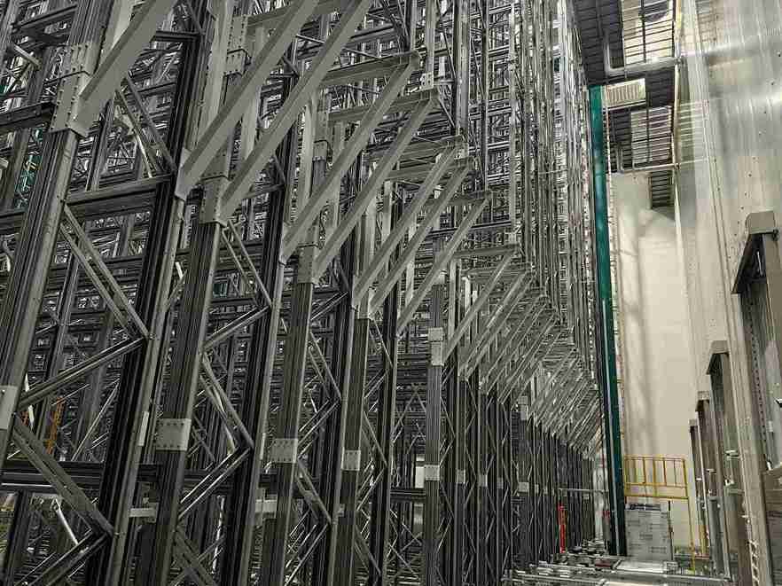
Die high-bay warehouse represents one of the most significant engineering achievements in modern logistics infrastructure. These towering automated storage facilities, often reaching heights of 30 meters or more, have revolutionized how industries store, retrieve, and manage inventory. At the heart of China’s approach to designing these complex systems lies JB/T 9018-1999 “High-bay warehouses—Design rules,” a mechanical industry standard that established the fundamental requirements for rail-guided high-bay racked warehouses.
This comprehensive guide examines every facet of high-bay warehouse design as codified in JB/T 9018-1999, while also exploring the evolution toward current standards including JB/T 9018-2011 and the national standard GB/T 39681-2020. From structural calculations and material specifications to safety protection devices and throughput capacity calculations, this article provides warehouse engineers, facility designers, and logistics professionals with the authoritative reference needed to design, evaluate, and optimize high-bay warehouse systems.
The principles established in these standards remain as relevant today as when first published. Whether designing a new high-bay warehouse, retrofitting an existing facility, or simply seeking to understand the technical foundations of automated warehousing, this guide delivers the comprehensive knowledge required for success in this specialized field.
H1: Understanding the High-Bay Warehouse: Historical Context and Standard Evolution
H2: The Origins of JB/T 9018-1999
Published on June 28, 1999, and implemented on January 1, 2000, JB/T 9018-1999 replaced the earlier ZB J83 015-1989 standard. The revision maintained the core technical content while incorporating editorial improvements that enhanced clarity and usability. For nearly a decade and a half, this standard served as the definitive design reference for high-bay warehouse systems throughout China’s rapidly industrializing economy.
The standard’s scope explicitly applies to warehouses composed of steel-structure racks and rail-guided aisle stacker cranes, with the primary function of storing unit loads. This focus on rail-guided, high-bay configurations reflects the predominant approach to automated warehousing that has become synonymous with modern logistics operations worldwide.
H2: The Evolution to JB/T 9018-2011 and GB/T 39681-2020
The transition from JB/T 9018-1999 to JB/T 9018-2011 marked a significant milestone in the standardization of automated storage and retrieval systems. Published on December 20, 2011, and implemented on April 1, 2012, the newer standard broadened its scope to include automated storage and retrieval systems generally, rather than focusing exclusively on rail-guided configurations. It updated references to current structural design standards and incorporated lessons learned from over a decade of real-world implementation experience.
The most significant recent development is GB/T 39681-2020 “Stereo warehouse racking system design specification,” a national standard published on December 14, 2020, and implemented on July 1, 2021. This standard represents the highest level of authority in the Chinese standards hierarchy for high-bay warehouse racking systems. It provides comprehensive requirements for racking system terminology, materials, loads and load combinations, rack design, and testing methods, and applies to racking systems made from cold-formed or hot-rolled steel sections primarily subjected to static loads.
H2: The Global Context for High-Bay Warehouse Standards
While China’s JB/T 9018 series and GB/T 39681-2020 provide the domestic framework, high-bay warehouse design also operates within a broader international standards environment. The European standard EN 528 governs safety requirements for storage and retrieval cranes, while ASME B30.13-2022 provides guidance for on-site storage and retrieval machines in the United States. The German guideline VDI 4480 offers methods for determining the throughput of automatic warehousesund VDI 3564 provides fire protection recommendations specifically for high-bay warehouses.
For engineers designing high-bay warehouse systems that must comply with multiple regulatory regimes, understanding the relationships and differences between these standards is essential. The principles established in JB/T 9018-1999 align broadly with international best practices while reflecting the specific conditions and requirements of the Chinese industrial context.
H1: Foundational Terminology for High-Bay Warehouse Design
H2: Core Definitions
Understanding the precise terminology defined in JB/T 9018-1999 is essential for proper interpretation and application of the standard. The vocabulary established in this document remains fundamental to high-bay warehouse engineering.
High-Bay Racked Warehouse (高架仓库)
A warehouse primarily composed of a steel-structured high-bay racking system, equipped with stacker cranes and auxiliary equipment. This definition emphasizes the integral relationship between the racking structure and the material handling equipment that operates within it.
Racking (货架)
The complete steel structure used for storing goods and supporting the stacker crane. In a high-bay warehouse, the racking system is not merely passive storage—it must withstand significant dynamic loads from crane operations while maintaining dimensional stability.
Integrated Racking (整体式货架)
A structural system that supports both the goods load and serves as the building structure, bearing roof and wall loads. This “rack-supported building” approach maximizes space utilization by eliminating separate structural columns, making it particularly attractive for very tall high-bay warehouse installations.
Separate Racking (分离式货架)
An independent structural system that supports only the goods load, with the building envelope provided by a separate structure. This configuration offers greater design flexibility and is more common in retrofit applications or where local building codes require independent structural systems.
Storage Bay (货格)
The unit space within the racking system designated for storing goods. Each bay represents a discrete storage location within the larger high-bay warehouse framework.
Storage Position (货位)
The specific location within a storage bay that holds one unit load. In a typical high-bay warehouse, each bay may contain multiple storage positions across different vertical levels.
Rail-Guided Aisle Stacker Crane (有轨巷道堆垛起重机)
A crane that travels along rails within the aisle, accessing storage positions to perform loading and unloading operations. The stacker crane is the heart of any high-bay warehouse, responsible for the rapid, precise movement of unit loads throughout the facility.
H2: Directional and Dimensional Terminology
The standard defines three critical directional orientations that govern every aspect of high-bay warehouse design:
B Direction
The direction perpendicular to the stacker crane’s travel path in the warehouse plan. This dimension determines the width of the storage aisles and the depth of the racking bays.
L Direction
The direction parallel to the stacker crane’s travel path in the warehouse plan. This dimension determines the length of the aisles and the overall footprint of the high-bay warehouse.
Row (排), Column (列), and Tier (层)
Row: Unit of storage positions in the B direction
Column: Unit of storage positions in the L direction
Tier: Unit of storage positions in the vertical direction
These three dimensions collectively define the storage capacity of any high-bay warehouse. The product of rows, columns, and tiers yields the total number of storage positions available.
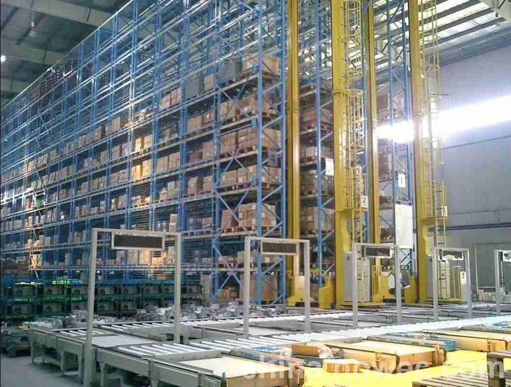
H2: Operational Definitions
Working Cycle (作业循环)
The complete process from the stacker crane’s home position through performing a storage or retrieval operation and returning to the home position. The efficiency of working cycles directly determines the throughput capacity of a high-bay warehouse.
Single Working Cycle (单一作业循环)
A cycle involving either a single storage or a single retrieval operation. This is the simpler of the two cycle types and forms the basis for calculating minimum cycle times.
Compound Working Cycle (复合作业循环)
A cycle involving both a storage and a retrieval operation in sequence. Compound cycles are more efficient than single cycles because they combine two operations in one round trip, significantly improving the overall throughput of a high-bay warehouse.
Home Position (原始位置)
The stacker crane’s designated position before commencing operations. The location of the home position relative to the storage array affects average travel distances and, consequently, overall system throughput.
H1: Unit Load Specifications: The Foundation of High-Bay Warehouse Design
Every high-bay warehouse is designed around the characteristics of the unit loads it will handle. JB/T 9018-1999 establishes critical parameters that fundamentally influence every aspect of system design.
H2: Weight Limitations
The weight of a unit load, including the pallet, must not exceed the stacker crane’s rated lifting capacity. This requirement has cascading implications throughout the high-bay warehouse design process:
Rack structural requirements: Heavier loads require stronger uprights, heavier gauge steel, and more robust connections
Stacker crane motor sizing: The lifting mechanism must be capable of accelerating and decelerating the maximum load safely
Floor loading calculations: The foundation must support the combined weight of racks, loads, and equipment
Foundation design specifications: Soil conditions and foundation design must accommodate the concentrated loads imposed by rack uprights
A high-bay warehouse designed for 1.6-ton unit loads cannot safely accommodate 2-ton loads without structural modifications. This is why accurate load specifications are essential at the earliest stages of high-bay warehouse planning.
H2: Recommended Dimensions
JB/T 9018-1999 recommends three standard unit load dimensions that have become industry benchmarks:
| Dimension (mm) | Common Application |
|---|---|
| 800 × 1000 | Smaller footprint, high-density storage |
| 800 × 1200 | European standard pallet compatible |
| 1000 × 1200 | Standard ISO pallet, most common |
Die 1000 × 1200 mm configuration has emerged as the predominant choice for most high-bay warehouse applications, reflecting the widespread adoption of the ISO standard pallet in global logistics. However, the 800 × 1200 mm dimension remains popular in applications where European pallet standards prevail.
These dimensions are not merely recommendations—they are the basis for calculating bay widths, aisle clearances, and overall high-bay warehouse footprint. Deviating from these standards requires custom engineering and typically increases costs.
H2: Dimensional Tolerances
Perhaps the most demanding requirement in this section is the tolerance specification: unit load external dimensional deviations must not exceed 5 mm. This stringent requirement ensures:
Reliable stacker crane positioning: The crane’s forks must engage the load precisely
Clearance maintenance between adjacent loads: The 50-100 mm clearances specified elsewhere assume consistent load dimensions
Prevention of operational jams: A load that is even slightly oversized can become wedged in the racking
Consistent automated handling: Automated systems cannot compensate for dimensional variations
For operators of high-bay warehouse systems, this tolerance requirement underscores the importance of quality control in pallet and load preparation. Even minor damage to a pallet can render a unit load unsuitable for automated handling.
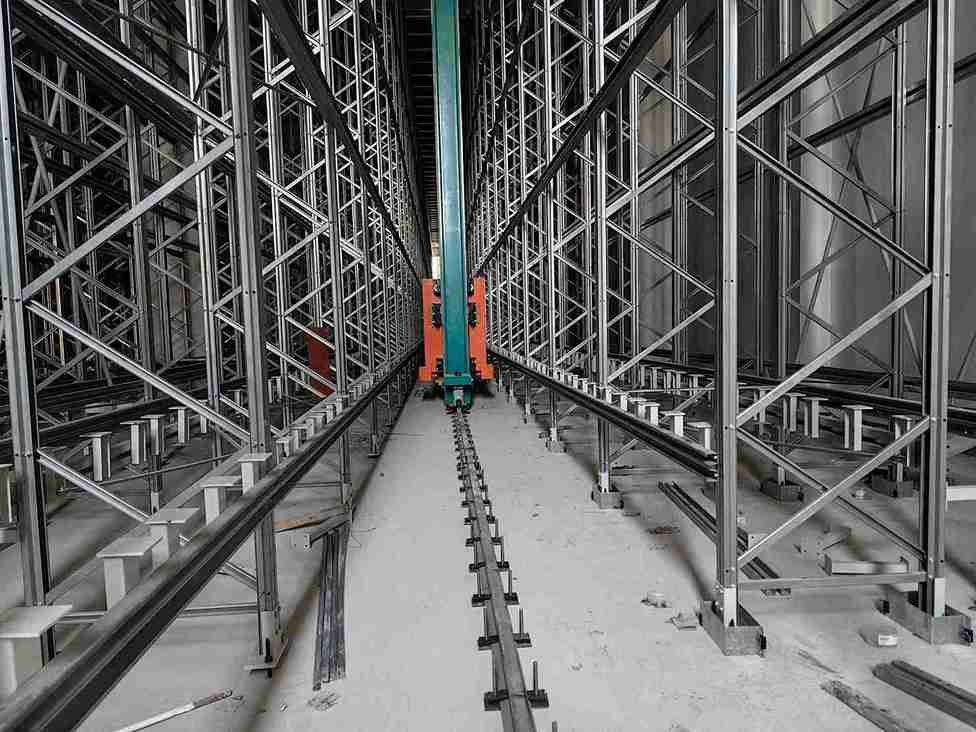
H1: Racking System Design: The Structural Backbone of Every High-Bay Warehouse
The racking system is the most visible and substantial component of any high-bay warehouse. Its design must balance competing requirements for strength, stability, accessibility, and cost.
H2: Structural Calculation Standards
The racking structure must be designed according to established Chinese standards that ensure structural integrity under all anticipated loading conditions:
GBJ 17-1988 (Steel Structure Design Specification) for ordinary section steel materials
GBJ 18-1987 (Technical Specification for Cold-Formed Thin-Wall Steel Structures) for thin-wall steel sections
These standards address dead loads, live loads, wind loads, and seismic forces. In a high-bay warehouse, the vertical loads from stored goods are the primary design consideration, but lateral loads from crane operations and seismic events can be equally significant.
Modern high-bay warehouse designs increasingly employ cold-formed thin-wall steel sections because they offer an excellent strength-to-weight ratio. However, these sections require careful attention to connection design and local buckling considerations.
H2: Material Specifications
Primary Structural Steel
The standard specifies Q235-A or Q235-A·F from GB/T 700-1988 as the primary material for load-bearing structural components. Key requirements include:
Guaranteed tensile strength
Guaranteed elongation
Guaranteed yield point
Limited sulfur and phosphorus content
Carbon content limits for welded structures
Cold-bending test certification for cold-formed components
Low-Temperature Considerations
For operating environments at or below -20°C, load-bearing structural components must use killed steel with impact toughness not less than 0.30 N·m/mm² at the service temperature. This requirement prevents brittle fracture in cold conditions—a critical safety consideration for high-bay warehouse facilities in northern China.
Modern Material Practice
While JB/T 9018-1999 specifies Q235-A steel, modern high-bay warehouse design often employs higher-grade materials:
Q235-B: Provides better low-temperature performance
Q345: Higher strength-to-weight ratio for taller racks
High-strength low-alloy steels: For specialized applications
The choice of material must consider operating temperature range, seismic requirements, rack height, load magnitude, and cost constraints. For very tall high-bay warehouse installations, higher-strength materials may be economically justified by the reduction in steel weight.
H2: Load Classifications
Separate Racking Loads
For separate racking systems, JB/T 9018-1999 specifies loading rates in Table 1:
| Load Type | Loading Rate (%) |
|---|---|
| Normal Working Load | 100 |
| Special Load | 80 |
The 80% loading rate for special conditions, primarily seismic events, accounts for the realistic probability that racks will not be fully loaded during an earthquake. However, this provision has been the subject of professional discussion: while reasonable for seismic calculations along the aisle direction, it may underestimate seismic loads perpendicular to the aisle, where full loading is more likely.
Integrated Racking Loads
Integrated racking systems must comply with GBJ 9-1987 (Building Structure Load Specification), reflecting their dual role as both storage structure and building support.
H2: Dimensional Conventions
The standard establishes comprehensive dimensional notation for both integrated and separate high-bay warehouse configurations.
Integrated Racking Dimensions (Table 2)
| Code | Name |
|---|---|
| L | Total warehouse length |
| L₁ | Total rack length |
| Lc₁ | Empty length at loading/unloading end |
| Lc₂ | Empty length at non-loading/unloading end |
| B₁ | Total width at loading/unloading end |
| B₂ | Total width at non-loading/unloading end |
| H | Total warehouse height |
| P | Track gauge |
Separate Racking Dimensions (Table 3)
| Code | Name |
|---|---|
| L₁ | Total rack length |
| B₁ | Total rack width |
| H₁ | Total rack height |
| P | Track gauge |
These dimensional conventions ensure clear communication between all parties involved in high-bay warehouse design, from architects and structural engineers to equipment suppliers and facility operators.
H1: Stacker Crane Specifications: The Heart of the High-Bay Warehouse
The stacker crane is the workhorse of any high-bay warehouse. Its performance characteristics directly determine the facility’s throughput capacity and operational efficiency.
H2: Rated Lifting Capacity
JB/T 9018-1999 defines rated lifting capacities that have become industry standards:
| Type | Rated Lifting Capacity (t) |
|---|---|
| Order Picking Type | 0.1, 0.25 |
| Unit Load Type | 0.1, 0.25, 0.5, 1, 1.6, 2 |
| Combined Picking-Unit Load Type | — |
For unit loads exceeding 2 tons, capacities must comply with GB/T 783-1987 (Maximum Lifting Capacity Series for Lifting Appliances). In modern high-bay warehouse practice, capacities up to 5 tons are not uncommon, particularly in heavy industry applications.
The selection of lifting capacity involves a trade-off: higher capacity cranes are more expensive and heavier, requiring stronger racking and foundations, but they enable the handling of larger unit loads, potentially reducing the number of crane trips required.
H2: Speed Specifications
The standard establishes rated speeds for the horizontal travel mechanism:
| Mechanism | Speed Value (m/min) |
|---|---|
| Horizontal Travel Speed (v₁) | 25, 31.5, 40, 50, 63, 80, 100, 125, 160 |
These speeds represent the standard series, with actual selection depending on:
Desired throughput rates
Aisle length
Load characteristics
Operational requirements
Faster horizontal travel speeds reduce cycle times but require more powerful motors, stronger racking to withstand dynamic loads, and more sophisticated control systems for accurate positioning. In a typical high-bay warehouse, horizontal travel accounts for the majority of cycle time, making speed optimization a priority.
H2: Structural Calculation Parameters
Design Working Cycle Count
The design working cycle count serves as the basis for calculating structural fatigue and mechanical component life:
Known operating conditions: Calculate based on actual usage
Unknown operating conditions: Verwenden Sie 5 × 10⁶ cycles as the design basis
This cycle count reflects the expected service life of the high-bay warehouse equipment. For facilities with high utilization rates, the actual cycle count may be significantly higher, requiring more robust component design.
Additional Load Coefficient
Additional load coefficients for stress calculations must comply with GB/T 3811-1983 (Crane Design Specification). These coefficients account for dynamic effects, load combinations, and other factors that increase stresses beyond static calculations.
Average Acceleration/Deceleration
The standard specifies acceleration limits based on cargo characteristics:
| Cargo Condition | Average Acceleration/Deceleration (m/s²) |
|---|---|
| Easily spilled cargo / Operator frequently riding | ≤ 0.5 |
| Stable cargo (boxed pallets, etc.) | ≤ 1.0 |
These limits prevent load shifting or damage during operation while optimizing cycle times. For high-bay warehouse systems handling fragile or unstable loads, the lower acceleration limit may significantly impact throughput capacity.
H2: Type Designation
Stacker crane types must comply with JB/T 2960-1999 (Types and Basic Parameters for Aisle Stacker Cranes). This standard provides the classification framework for different crane configurations, including:
Single-mast vs. double-mast designs
Cabin-mounted vs. floor-mounted controls
Manual, semi-automated, and fully automated operation modes
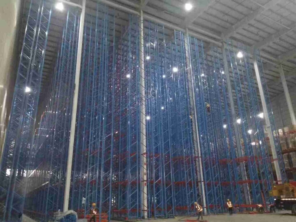
H1: Electrical Equipment Requirements for High-Bay Warehouse Operations
The electrical systems of a high-bay warehouse must be designed for reliability, safety, and maintainability in an environment characterized by continuous operation and high demands on power quality.
H2: Power Supply
Flexible Cable Supply
When using flexible cable power supply, copper-core stranded conductors are required:
Rubber-insulated cables or wires for general use
Plastic-insulated wires only for:
Operator cabin internal use
Electrical control box internal use
Low-current circuits
Control circuits
The preference for copper conductors reflects their superior conductivity and resistance to fatigue failure under the repeated flexing that occurs during stacker crane operation.
Conductor Rail Supply
For conductor rail power supply, safety protection measures such as insulating sheaths or enclosures must be provided for current collectors and conductor rails. This prevents accidental contact with live conductors, a critical safety consideration in the confined spaces of a high-bay warehouse aisle.
H2: Control Panel Layout
Control Panel Height
The standard specifies control panel height from the operator’s standing surface:
| Operator Posture | Control Panel Height (mm) | Notes |
|---|---|---|
| Seated | 600-900 | Horizontal or inclined panel |
| Standing | 1100-1300 | Vertical panel (center calculation) |
| Standing | 1300-1600 | Vertical panel (center calculation) |
These ergonomic requirements reduce operator fatigue and improve reaction times during high-bay warehouse operations.
Control Direction Conventions
The standard mandates specific control direction conventions to ensure intuitive operation:
Control directions must follow standardized patterns
Operating directions must be clearly labeled on the control panel
Consistent control conventions reduce the risk of operator error, particularly important in high-bay warehouse environments where a single mistake can cause significant damage.
Emergency Stop
An emergency stop button must be provided that immediately cuts the main power supply:
Red mushroom-type button
Located on the right front side of the operator
This placement ensures rapid access in emergency situations, potentially preventing injuries or equipment damage.
H1: Warehouse Building Requirements for High-Bay Warehouse Facilities
The building that houses a high-bay warehouse must meet requirements far exceeding those of conventional warehouses. The precision required for automated operations demands exceptional attention to floor flatness, foundation stability, and environmental control.
H2: Floor Flatness Tolerances
Before rack installation, floor flatness must meet stringent tolerances:
| Length/Width Dimension (m) | Allowable Deviation (mm) |
|---|---|
| ≤ 50 | ±10 |
| ≤ 150 | ±15 |
| > 150 | ±20 |
Additionally, local flatness must be less than 4 mm over any 2 m span. These stringent requirements ensure:
Proper stacker crane alignment
Smooth horizontal travel
Prevention of rack distortion
Reliable automated operation
For very narrow aisle (VNA) high-bay warehouse systems, floor flatness requirements are even more demanding. The stacker crane’s guidance system relies on the rails being precisely positioned and maintained, which is impossible without a flat, stable floor.
H2: Foundation Settlement
Under maximum load, rack foundation floor settlement deformation must be less than 1/1000. The standard further requires that the local deformation slope (tan α) of foundation bearing plates or beams must not exceed 1/2000 under maximum working load. If deformation exceeds this value, the rack strength calculation must account for the deformation and resulting additional stresses.
This requirement effectively mandates proper soil investigation and foundation design—inadequate foundation preparation is a leading cause of high-bay warehouse system failure. The concentrated point loads from rack uprights can be enormous, and without proper foundation design, differential settlement can cause rack misalignment, binding of stacker crane movements, and ultimately structural failure.
H2: Environmental Systems
The standard requires that:
Lighting, HVAC, and utilities comply with applicable regulations and user requirements
Fire protection systems comply with national laws and standards
For high-bay warehouse facilities storing temperature-sensitive goods, HVAC requirements may dominate the design. Cold storage high-bay warehouses, operating at temperatures as low as -25°C, present particular challenges for structural design, material selection, and equipment operation.
H2: Fire Protection
Fire protection is a critical concern for any high-bay warehouse. The combination of high-value inventory, limited accessibility, and rapid fire spread in rack storage configurations creates unique risks.
Chinese regulations require that high-bay warehouses have a fire resistance rating of at least Level 2, with some facilities requiring Level 1. For very tall high-bay warehouse facilities exceeding 50 meters in height, Level 1 fire resistance is mandatory.
Modern high-bay warehouse fire protection often includes:
In-rack sprinklers for early suppression
High-density ceiling systems for overall protection
Smoke and heat control systems for visibility and structural protection
Commodity classification to determine appropriate protection levels
The German guideline VDI 3564 provides comprehensive recommendations for fire protection in high-bay warehouses, addressing planning, construction, and operation. These principles are increasingly being adopted in international practice.
H1: Safety Protection Devices: Safeguarding High-Bay Warehouse Operations
Safety is paramount in high-bay warehouse design. The combination of heavy moving equipment, elevated loads, and confined spaces creates numerous hazards that must be addressed through engineering controls.
H2: Travel End Protection Devices
To ensure automatic power cutoff and stopping when the stacker crane reaches the travel limit, three devices are required:
Travel End Speed Limiter
Forces disengagement of high and medium speeds as the stacker crane approaches the aisle end. This progressive slowing reduces impact forces and allows for more precise positioning.
Travel End Limit Switch
Activates the travel mechanism brake before collision with the end stop. This serves as the primary stopping mechanism during normal operation.
End Stop (Buffer)
End stops must have strength calculated according to GB/T 3811-1983. Additionally, both the end stop and stacker crane must provide buffering capability to prevent tipping or damage. Buffers or other devices should be installed at aisle ends when necessary.
These three devices work in sequence: the speed limiter slows the crane, the limit switch stops it, and the buffer absorbs any residual energy if the first two fail. This layered approach ensures safety even in the event of component failure.
H2: Hoist Limit Switches
To prevent over-hoisting and over-lowering:
Upper limit switches: Minimum of 2 devices
Lower limit switches: Minimum of 1 device
The redundancy in upper limit switches reflects the greater hazard of over-hoisting, which could cause the load platform to collide with the roof structure or rack top.
H2: Position Detection
For automated stacker cranes, a position detector must be installed that can automatically determine whether the target storage position is occupied. This prevents:
Double-storage collisions
Attempted retrieval from empty positions
Operational errors
Modern high-bay warehouse systems often employ multiple position detection technologies, including laser ranging, barcode reading, and RFID, to ensure reliable position verification.
H2: Rope Break Protection
For stacker cranes without an operator cabin, a rope break protection device must be provided to prevent load platform falling in the event of hoist rope or chain failure. This device typically uses mechanical wedges or friction brakes that engage automatically when rope tension is lost.
H2: Speed Limiting Anti-Fall Device
For stacker cranes with an operator cabin, a speed limiting anti-fall device is mandatory. This device must stop the load platform’s descent and cut the control circuit if the descent speed exceeds 1.15 times the rated speed due to:
Brake failure
Load-carrying component damage
Other malfunctions
The 1.15 threshold provides a margin above normal operating speed while still detecting dangerous conditions early enough to prevent injury.
H2: Rope Slack and Overload Protection
To prevent operational issues from excessive or insufficient rope tension, both rope slack und overload protection devices must be installed. Rope slack detection prevents the rope from coming off drums or sheaves, while overload protection prevents the crane from attempting to lift loads exceeding its capacity.
H2: Interlock Protection
Electrical interlocks must ensure that when the fork is extended (not returned to zero position), the following are de-energized:
Horizontal travel mechanism
High-speed hoist (or lowering) mechanism
This prevents the dangerous situation where a crane with extended forks moves horizontally or vertically at high speed, potentially striking rack structures or stored goods.
H2: Safety Ladder
Stacker cranes must be equipped with a safety ladder enabling operator evacuation from the load platform or cabin in emergency situations. This ladder must be accessible from both the platform and the floor level, providing a means of escape even if the crane is stopped at an elevated position.
H2: Additional Safety Considerations
Modern high-bay warehouse safety systems often include:
Anti-sway control to stabilize suspended loads
Precision positioning systems for accurate load placement
Sensor self-diagnosis to detect failures before they cause accidents
Safe position and motion monitoring throughout the aisle
The safety of high-bay warehouse operations depends not only on these devices but also on proper maintenance, operator training, and adherence to safe operating procedures.
H1: Critical Interface Dimensions in High-Bay Warehouse Design
Proper coordination between building structure, racking, and stacker crane is essential for safe and efficient high-bay warehouse operation. JB/T 9018-1999 establishes specific dimensional requirements that govern these interfaces.
H2: Travel End Clearance
At the horizontal travel end (with the stacker crane and end stop in compressed state), the minimum distance between the stacker crane’s outermost point below 1800 mm height and the building structure must be greater than 400 mm. This clearance:
Provides safe egress for personnel
Prevents pinch points
Allows for maintenance access
The 1800 mm height threshold corresponds to typical human height, ensuring that the most hazardous pinch points are located above head height.
H2: Roof Clearance
For separate racking systems, the distance from the rack top to the roof truss bottom chord must meet installation requirements but shall not be less than 200 mm. This clearance accommodates:
Installation tolerances
Thermal expansion
Maintenance access
In very tall high-bay warehouse installations, thermal expansion can be significant, and additional clearance may be required.
H2: Lateral Clearance
The gap between the stacker crane’s outermost point (in the aisle width direction) and the rack columns or stored goods should generally be selected within the range of 50 to 100 mm, but must not be less than 50 mm.
This clearance represents a critical design parameter: too little clearance risks collisions, while too much clearance wastes valuable floor space. Modern high-bay warehouse systems often push toward the minimum clearance to maximize storage density, requiring tighter manufacturing tolerances and more precise control systems.
H1: Storage Bay and Cargo Relationship in High-Bay Warehouse Design
The relationship between storage bay dimensions and cargo dimensions determines the storage density and operational reliability of any high-bay warehouse.
H2: Dimensional Notation
The standard defines comprehensive dimensional notation for storage bay and cargo relationships:
| Code | Name |
|---|---|
| a₁ | Cargo length |
| a₂ | Effective bay length |
| a₃ | Lateral clearance |
| a₄ | Support width |
| a₅ | Horizontal clearance between cargo |
| b₁ | Cargo width |
| b₂ | Effective bay width |
| h₁ | Cargo height |
| h₂ | Vertical clearance above unit load |
| h₃ | Tier height |
| h₄ | Vertical clearance below unit load |
H2: Dimensional Requirements
Lateral Clearance (a₃)
Should generally be selected within the range of 50 to 100 mm. This clearance accommodates manufacturing tolerances, load deflection, and positioning errors while preventing contact between adjacent loads.
Support Width (a₄)
Must be greater than the lateral clearance (a₃). This ensures:
Adequate load support
Proper load distribution
Safe load transfer
The support width is typically provided by the pallet beams or shelves on which the unit load rests.
Upper Vertical Clearance (h₂)
Must ensure that cargo does not contact rack structural members when entering or leaving the storage position. This clearance must account for load deflection, manufacturing tolerances, and stacker crane positioning accuracy.
Lower Vertical Clearance (h₄)
Must ensure that the stacker crane fork can freely enter and exit the storage position. This clearance is typically the most critical vertical dimension, as the fork must pass between the load and the support surface.
These clearance requirements are not merely suggestions—they are essential operational parameters. Insufficient clearances lead to collisions, equipment damage, and operational downtime.
H1: Throughput Capacity Calculation for High-Bay Warehouse Systems
Throughput capacity is the single most important performance metric for any high-bay warehouse. JB/T 9018-1999 provides the methodology for calculating this critical parameter.
H2: Basic Throughput Formula
Throughput capacity is calculated using Equation (1):
n = 3600 / t_m
Where:
n = Number of unit loads (or pallets) entering or leaving the warehouse per hour
t_m = Average working cycle time (seconds)
This simple formula belies the complexity of accurately determining the average working cycle time, which depends on crane speeds, travel distances, and fixed-time operations.
H2: Average Single Working Cycle Time
The average single working cycle time is calculated using Equation (2):
t_m₁ = ½ [t(p₁) + t(p₂)] + t_0₁
Where:
t_m₁ = Average single working cycle time
t(p₁) = Round-trip travel time (horizontal + hoist) from home position to point p₁
t(p₂) = Round-trip travel time (horizontal + hoist) from home position to point p₂
t_0₁ = Sum of fixed-time operations in a single working cycle (positioning, position detection, fork operations, etc.)
The use of two representative points, p₁ and p₂, accounts for the distribution of storage positions throughout the high-bay warehouse. Typically, these points represent average and worst-case travel distances.
H2: Average Compound Working Cycle Time
The average compound working cycle time is calculated using Equation (3):
t_m₂ = t(p₁; p₂) + t_0₂
Where:
t_m₂ = Average compound working cycle time
t(p₁; p₂) = Travel time (horizontal + hoist) from home position to p₁, then to p₂, and finally returning to home position
t_0₂ = Sum of fixed-time operations in a compound working cycle (positioning, position detection, fork operations, etc.)
Compound cycles are significantly more efficient than single cycles because they combine two operations in one round trip. In a typical high-bay warehouse, compound cycles can increase throughput by 30-50% compared to single cycles.
H2: Practical Application
These calculations enable designers to:
Determine required stacker crane speeds
Size the number of stacker cranes needed
Validate throughput requirements
Optimize warehouse layout
Evaluate operational efficiency
For complex high-bay warehouse systems, throughput calculations are often supplemented by discrete-event simulation to account for the interactions between multiple cranes, conveyor systems, and other material handling equipment.
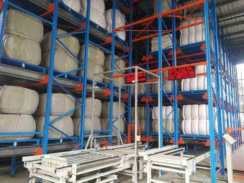
H1: Integrated vs. Separate Racking: A Critical High-Bay Warehouse Decision
The choice between integrated and separate racking systems has profound implications for high-bay warehouse design, construction, and operation.
H2: Integrated Racking (整体式货架)
In an integrated racking system, the racks serve as both the storage structure and the building structure, supporting roof and wall loads.
Vorteile:
Maximum space utilization: No separate structural columns are needed
Reduced construction cost: The rack serves as the building structure
Unified structural design: Single system for all loads
Potential for taller buildings: Rack-supported structures can be very tall
Benachteiligungen:
Less design flexibility: Rack layout is constrained by building requirements
More complex seismic analysis: The rack must perform as both storage and building structure
Difficult to modify or expand: Changes to the rack affect the building
Specialized design expertise required: Fewer engineers have experience with this approach
Integrated racking is most common in very tall high-bay warehouse facilities where the cost savings from eliminating separate building structure are significant.
H2: Separate Racking (分离式货架)
In a separate racking system, the racks support only the goods load, with the building envelope provided by a separate structure.
Vorteile:
Design flexibility: Rack layout can be optimized independently
Easier modification: Changes to the rack don’t affect the building
Simpler structural analysis: Each system can be designed independently
Simpler seismic design: The rack and building respond differently to earthquakes
Easier to phase construction: Building can be completed before racks are installed
Benachteiligungen:
Lower space utilization: Separate structural columns reduce available space
Higher construction cost: Separate building structure required
Potential for conflicts: Building and rack must be carefully coordinated
Separate racking is more common in retrofit applications or where local building codes require independent structural systems.
H1: Best Practices for High-Bay Warehouse Design and Operation
Drawing on decades of experience and the principles established in JB/T 9018-1999 and subsequent standards, industry best practices for high-bay warehouse design have evolved significantly.
H2: Design for Flexibility
The most successful high-bay warehouse designs anticipate future changes in storage requirements, product mix, and throughput demands. This includes:
Modular rack designs that can be reconfigured
Oversized power and control systems to accommodate future expansion
Flexible conveyor and sortation systems that can be adapted to changing material flows
Software systems that can support new features and integrations
H2: Invest in Software as Much as Hardware
Modern high-bay warehouse operations depend critically on software systems:
Warehouse Management Systems (WMS) for inventory tracking and order management
Warehouse Control Systems (WCS) for real-time equipment control
Material Flow Systems for optimizing material handling
3D Monitoring Systems for real-time visualization
The integration between these systems is often more important than the capabilities of any individual system.
H2: Train People Deeply
Even the most automated high-bay warehouse requires skilled personnel for maintenance, troubleshooting, and supervision. Training should cover:
Equipment operation and maintenance
Software systems and troubleshooting
Safety procedures and emergency response
Continuous improvement methodologies
H2: Build Collaboration Into Operations
High-bay warehouse operations involve multiple stakeholders: equipment suppliers, system integrators, software developers, and facility operators. Building collaborative relationships among these groups improves problem-solving and reduces downtime.
H2: Plan for Seismic Events
For high-bay warehouse facilities in seismic zones, seismic design is critical. Modern approaches include:
Ductile connections that can absorb seismic energy
Capacity design to ensure elastic behavior of critical components
Specialized seismic design strategies for rack-supported warehouses
Consideration of cross-aisle seismic loads which can be particularly damaging
H2: Address Fire Protection Comprehensively
Fire protection for high-bay warehouse facilities requires a comprehensive approach:
Commodity classification to determine appropriate protection
In-rack sprinklers for early suppression
High-density ceiling systems for overall protection
Smoke and heat control systems
Regular inspection and maintenance of fire protection systems
H1: Future Trends in High-Bay Warehouse Design
The high-bay warehouse industry continues to evolve, driven by technological advances, changing market demands, and new regulatory requirements.
H2: Higher and Denser Storage
The trend toward taller high-bay warehouse facilities continues, with some installations now exceeding 50 meters in height. This vertical expansion maximizes land utilization but places increasing demands on structural design, seismic performance, and fire protection.
H2: Increased Automation
The level of automation in high-bay warehouse facilities continues to increase. Beyond traditional stacker cranes, modern installations may include:
Four-way shuttle robots for high-density storage
Automated guided vehicles (AGVs) for horizontal transport
Robotic picking systems for order fulfillment
Artificial intelligence for optimization and predictive maintenance
H2: Integration with Industry 4.0
High-bay warehouse facilities are increasingly integrated with broader Industry 4.0 initiatives:
Real-time data analytics for performance optimization
Predictive maintenance to reduce downtime
Digital twins for simulation and training
Internet of Things (IoT) sensors for condition monitoring
H2: Sustainability and Energy Efficiency
Environmental concerns are driving improvements in high-bay warehouse energy efficiency:
LED lighting with motion sensors
Energy-efficient motors and drives
Solar panels on warehouse roofs
Regenerative braking on stacker cranes
H2: Enhanced Safety Standards
Safety standards for high-bay warehouse facilities continue to evolve. Recent developments include:
EN 528 for storage and retrieval crane safety
ASME B30.13-2022 for storage and retrieval machines
NFPA standards for fire protection
VDI guidelines for German practice
Schlussfolgerung
JB/T 9018-1999 “High-bay warehouses—Design rules” stands as a foundational achievement in Chinese industrial standardization. Though superseded by JB/T 9018-2011 and complemented by national standards like GB/T 39681-2020, its influence persists in the design philosophy, technical requirements, and safety principles that continue to guide high-bay warehouse design today.
The standard’s comprehensive coverage—from structural calculations and material specifications to safety protection devices and throughput calculations—establishes a complete framework for high-bay warehouse design. Its requirements for unit load dimensions, clearance specifications, and interface dimensions ensure interoperability between system components. Its safety provisions protect both personnel and equipment.
For warehouse designers, facility managers, and logistics professionals, understanding JB/T 9018-1999 provides essential context for:
Interpreting current standards
Evaluating legacy systems
Planning modernization projects
Ensuring regulatory compliance
Achieving operational excellence
The evolution from ZB J83 015-1989 to JB/T 9018-1999 to JB/T 9018-2011 to GB/T 39681-2020 reflects the continuous improvement of Chinese industrial standards, incorporating lessons learned, technological advances, and international best practices. As automated warehousing continues to evolve, the principles established in these standards remain as relevant as ever.
The high-bay warehouse of tomorrow will be taller, more automated, and more intelligent than today’s facilities. But the fundamental principles of sound design—structural integrity, operational reliability, and uncompromising safety—remain unchanged. The standards that codified these principles, beginning with JB/T 9018-1999, provide the foundation upon which the future of automated warehousing will be built.
Häufig gestellte Fragen
Q1: What is the maximum height for a high-bay warehouse designed under Chinese standards?
While JB/T 9018-1999 does not specify a maximum height, practical considerations including seismic design, foundation requirements, and fire protection typically limit heights to 30-40 meters for most applications. For facilities exceeding 50 meters in height, Level 1 fire resistance is mandatory. The rack-supported warehouse design can enable greater heights by eliminating separate structural columns.
Q2: How does the 5 mm unit load tolerance requirement affect pallet selection and maintenance?
The 5 mm tolerance requirement means that pallets must be manufactured to precise dimensions and maintained in good condition throughout their service life. Damaged or warped pallets may not fit properly in the racking or may cause operational jams. Many high-bay warehouse operators implement regular pallet inspection programs and reject pallets that exceed tolerance limits.
Q3: What are the key differences between the 1999 and 2011 versions of the JB/T 9018 standard?
The 2011 version broadened its scope to include automated storage and retrieval systems generally, rather than focusing exclusively on rail-guided configurations. It also updated references to current structural design standards and incorporated lessons learned from over a decade of real-world implementation experience. The 2011 standard remains current as of this writing.
Q4: How should seismic design be approached for a high-bay warehouse?
Seismic design for high-bay warehouse facilities requires careful consideration of both along-aisle and cross-aisle seismic loads. Modern approaches include ductile connections that can absorb seismic energy, capacity design to ensure elastic behavior of critical components, and specialized seismic design strategies for rack-supported warehouses. The 80% loading rate for special loads specified in JB/T 9018-1999 may be unconservative for cross-aisle seismic loads.
Q5: What fire protection measures are recommended for high-bay warehouse facilities?
High-bay warehouse fire protection typically includes in-rack sprinklers for early suppression, high-density ceiling systems for overall protection, and smoke and heat control systems. Commodity classification is essential to determine the appropriate protection level. Chinese regulations require a fire resistance rating of at least Level 2 for high-bay warehouses, with Level 1 required for facilities exceeding 50 meters in height. The German guideline VDI 3564 provides comprehensive recommendations for fire protection in high-bay warehouses.
Geelyracks specializes in the production of warehouse racks and is a global rack customization expert: https://geelyracks.com/
Wenn Sie perfekte CAD-Zeichnungen und Kostenvoranschläge für Lagerregale benötigen, Bitte kontaktieren Sie uns. Wir bieten Ihnen kostenlose Dienstleistungen und Angebote zur Planung und Gestaltung von Lagerregalen. Unsere E-Mail Adresse ist: jili@geelyracks.com